T-Carrier and SONET
Peter Dordal, Loyola University CS Department
T-carrier and SONET are both ways of transmitting digital data on a digital
carrier. They both represent STDM (Synchronous Time-Division
Multiplexing). This involves fixed-width interleaving of N
low-datarate channels onto one high-datarate line. In the course of one frame, each sender gets one timeslot
(usually equal-sized). 1 frame = N timeslots.
Timeslots are small (eg 1 byte), and have no addressing or
headers.
Input channels are assumed continuous:
senders send pad bytes if nothing else. (Note that in realtime voice
transmission, pad bytes represent silence,
but still need to be transmitted to maintain timing.) Encoding and decoding
are simple; no addressing is needed!!
T-carrier
In the telecommunications system, the first (and still common) STDM lines
are the T-carrier hierarchy (at least in the US; the
E1,etc hierarchy is used in Europe). The designation T1 describes the
hardware level; the designation DS1 (for Data Stream)
represents the logical signaling level. At the bit level, B8ZS
signaling is used. T1 was introduced in 1962; by 1970 these lines were used
for trunk lines on a large scale.
Note that B8ZS does not involve any insertion of extra bits, allowing for
strict preservation of the 8000-Hz "heartbeat".
The main advantage of digital over FDM is the absence of cumulative
distortion
A T1 line carries 24 DS0 lines. This works out to 24×64kbps = 1.536 mbps.
The actual bit rate of a T1/DS1 line is 1.544mbps, a difference of 8kbps.
The basic T1 frame is 193 bits, = 24 timeslots of 8 bits each, + 1 "framing"
bit. The frame rate is 8000 frames/sec (matching the voice sampling rate!),
meaning that every 1/8000 of a second the line carries 1 byte from each of
the 24 inputs, plus 1 bit. That works out to 8000 frames/sec × 193
bits/frame = 1,544,000 bits/sec = 1.544 mbps.
Note that the frame size 193 is a prime number. This is relatively common in
the telecom world, as opposed to the general-computing world where things
tend to be a power of 2, or a small multiple of a power of 2.
All we need is a 1-byte buffer for each input channel; these are sampled
round-robin. Some input channels can get 2 or more timeslots; buffering is
only slightly complicated.
That extra framing bit may not sound like much, and it is not. A group of 12
T1 frames is called a superframe; the framing bit is used to encode a
special bit-pattern, eg 0101 1101 0001, that can be used to identify lost
syncronization between the endpoints. (The pattern 0101 0101 0101 can be
used to synchronize frames, but not superframes).
24×64kbps = 1.536 mbps, DS1 = 1.544; difference (due to the framing bit) is
8kbps (1 bit/frame, × 8000 frames/sec)
framing-search mode: used for initial synchronization and when
synchronization is lost. We know a frame is 193 bits; we examine every bit
of each frame until we find one bit that consistently shows the framing
pattern.
When T1 lines are used to carry voice data, five frames out of six carry
8-bit PCM (µ-law in the US). Every sixth frame has the low-order bit taken
as a signaling bit; it is set to 0 on delivery. This is why modems just get
56kbps, not 64 kbps.
digital mode: 8th bit in every
byte is an indicator of user data v control; lots of room for stuffing but
with 8/7 overhead.
digital mode sync byte
Full-line digital mode: use 23 bytes per frame for data; 24th byte is used
for framing indicator that allows faster recovery than the 1-bit-per-frame
method.
Note from wikipedia:
allegedly in 1958 there was internal AT&T debate as to whether T1 lines
should have 1 extra bit for
framing, or 1 extra byte.
Supposedly the 1-bit group won because "if 8 bits were chosen for OA&M
function, someone would then try to sell this as a voice channel and you
wind up with nothing." Later, AT&T realized 1 byte would have made more
sense, and introduced various bit-stealing techniques; eg the low-order bit
of each sixth byte.
The main service of a T1 line is not
simply to provide a 1.5mbit data rate; there are much cheaper ways to do
that. The point of a T1 line is that the system provides extremely low delay
for each voice line: possibly less than a millisecond over the actual path
propagation delay. Buffering is essentially zero!
It is not likely that sub-millisecond delay
was part of the original justification for T1; it is more likely that the
byte-at-a-time transmission strategy was chosen simply because, in 1960,
buffering was rather expensive. In fact, a simple mechanism for
multiplexing 24 analog voice lines over one T1 line was to use a
single sampler that sampled each input line in turn, making 24 samples in
1/8000 second.
What if one of the inputs runs slow?
Naive outcome: we will duplicate a byte every now and then, from the slow
source. Ultimately, there is no easy fix for slow real-time streams. Note,
however, that it is easy to send packets over a single TDM channel
without slow-source worries! All we have to do is pre-buffer the entire
packet, so its next byte is always available. Alas, while this approach can
be used to eliminate the possibility of one link's running slow during the
time it takes to send one packet (thus corrupting that packet), it does mean
that we have to adopt a store-and-forward strategy at each switch: the
packet must be fully received and buffered for the next link.
DS lines are said to be plesiochronous:
close to synchronous, but with some reasonable tolerance for error. This is
usually pronounced Ples-ee-AH-krun-ous, to make it akin to SYN-krun-ous, but
some do pronounce it Ples-i-oh-KRON-us.
In plesiochronous lines, pulse stuffing
is used to accommodate minor timing incompatibilities. If the inbound links
run slightly slow, extra bits/bytes will be inserted to take up the slack.
The outbound link will have some extra bandwidth capacity; that is, it will
run slightly fast, so there will be room for pulse stuffing even if the
inbound links run slightly faster than expected. We need either applications
that will tolerate occasional bad data (voice) or else we need some way of
encoding where the extra stuffed bits/bytes have been put. Actually, pulse
stuffing in the real world pretty much requires that we can always identify
the stuffed bits.
Table 8.3: North American DS-N hierarchy
DS0
|
64kbps voice line |
DS1
|
1544 kbps, = 8×24 + 1 = 193 = 1544/8
bits/frame |
DS2
|
6312 kbps, 789 b/f = 96 bytes + 21
bits = 4×DS-1 + 17 bits
Actually 1176 bits per DS2 M-frame |
DS3
|
44736 kbps, 5592 b/f = 24×28 bytes +
27 bytes
= 7 DS2 + 69 bits
Actual frame size is 4704 bits, rate 106.402 microseconds
|
bit-stuffing: flag bits indicate whether certain bytes have data or padding
Allowable clock drift: 1 part in 2 × 10⁻⁵, or, for a DS1, 30
bits/sec
DS1→DS2 multiplexing
Reference: DS3fundamentals.pdf.
This is just plain weird. If nothing else, it should convince you that telco
engineers think in bits, not
bytes.
Note from Stallings (p 253 in 9th edition)
Pulse
Stuffing ... With pulse stuffing, the outgoing data rate of the
multiplexer, excluding framing bits, is higher than the sum of the maximum
instantaneous incoming rates. The extra capacity is used by stuffing extra
dummy bits or pulses into each incoming signal until its rate is raised to
that of a locally generated clock signal. The
stuffed pulses are inserted at fixed locations in the multiplexer frame
format so that they may be identified and removed at the demultiplexer.
But how do you tell when a bit was stuffed, and when it was not? Variability
(sometimes stuffing, sometimes not) is essential
if this technique is going to allow us to "take up slack".
Here are the details for how pulse-stuffing is used to multiplex four DS1
signals onto a DS2 signal, so that the DS1 signals can be recovered exactly.
First, the multiplexing is completely asynchronous; we do not
align on the 193-bit DS1 frame boundaries.
A DS2 stuff block is 48 bits of
data, 12 from each DS1, interleaved round-robin at the bit
level, plus an overhead (OH) bit at the front for 49 bits in all. (We'll
revisit these OH bits below; each such bit is designated either an M-bit, a
C-bit, or an F-bit, based on position.)
An M-subframe is six stuff-blocks,
holding 72 bits of each DS1, total 288+6=294 bits (294 = 6×49)
An M-frame is four subframes (M1,
M2, M3, M4), holding 288 bits of each DS1,
total 294×4=1176.
The DS2 line will send one M-frame about every 186 μsec, which is not
synchronized with the 125 μsec frame rate of T1 lines.
Each M-frame can accomodate up to 1 "stuff bit" per DS1 input. A stuff bit
is a bit that upon demultiplexing does not
belong to that DS1 stream, representing an opportunity for that input to run
slow. The DS2 output stream runs slightly fast (ie DS1 inputs are "slow"),
so stuff bits always represent "missed" bits. There is no way to handle
inputs running fast.
If the input buffer is running low on bits, we insert a stuffed bit to give
it a chance to catch up.
Naming the overhead bits:
In each M-subframe, there are six OH bits: ⟨M, C, F, C, C, F⟩.
M0
|
C
|
F0
|
C
|
C
|
F1
|
M1
|
C
|
F0
|
C
|
C
|
F1
|
M1
|
C
|
F0
|
C
|
C
|
F1
|
Mx
|
C
|
F0
|
C
|
C
|
F1
|
In this diagram, each cell contains a stuff block, with leading bit M, C or
F. Each row respresents an M-subframe; the rows represent subframes M1,
M2, M3, M4. The entire grid is an M-frame.
There are 4 M-bits in an M-frame, spelling out the bit pattern 011x, where x
varies.
The F-bits are for frame alignment; the first is always 0 and the second is
always 1.
Stuffing for input stream i is done in M-subframe Mi, i<4.
(Note that each subframe has 288 bits from each input DS1; Mi is
not reserved for the ith stream!) Up to four bits (one from each input T1)
can be stuffed in each M-frame.
If the three C-bits of that subframe (ith row) are all 1's, then the first
bit of the ith input stream in the last stuff block is stuffed; ie is not
real. If the C-bits are all 0's, then there was no stuffing.
Actual use: 2 out of 3 1's, versus 2 out of 3 0's. (WHY WOULD WE DO THAT???
Isn't any bit error equally
fatal??)
Note the size of the blocks never changes.
With four DS1's, the data rate for a DS2 needed is 4×1.544×49/48 =
6.30466666.. Mbps
But the actual DS2 rate is 6.312 Mbps = 8 kbps × 789
We stuff bits as necessary to take up the slack.
total DS2 bits per second: 6312000
DS1×4 data bits per second: -6176000
DS2 overhead bits per second - 128816
________
Total stuff bits:
7184
Divided by 4:
1796 bps per DS1
At 8000 frames/sec for DS1, that's roughly 1 stuff bit every 4.5 T1 frames,
or 1 bit every 860 bits, per T1 input. This works out to about 1.3 stuff
bits for every M-frame: for one T1 input, we have a stuff bit roughly once
every 860/288 ≃ 3 M-frames, and there are 4 inputs.
DS2→DS3: Same strategy is possible, except nowadays this is generally done
as an integrated process multiplexing 28 DS1's into a DS3. So the DS3 stuff
bits are never needed (all the
slack is taken up at the DS1→DS2 level), so they've been adopted for
line-signaling purposes.
As we move higher up the hierarchy, more and more stuff bits are needed. A
different approach is used for very-high-speed links.
SONET
Good reference: sonet_primer.pdf
Sonet is said to be truly synchronous:
timing is supposed to be exact, to within ±1 byte every several frames.
Bit-stuffing (pulse stuffing) was seen by the telecommunications industry as
a major weakness in the T-carrier system, introducing more and more wasteful
overhead as the multiplexing grew. The core issue is that when you combine
several "tributaries" into one larger data stream, your big stream needs
extra capacity to be able to handle speedups and slowdowns in the inputs.
This wastes bandwidth, but even more importantly it wastes equipment.
SONET was an attempt to avoid this problem.
First look at SONET hierarchy: Stallings Table 8.4 (largely reproduced
below)
STS-1/OC-1
|
|
51.84 Mbps
|
STS-3/OC-3
|
STM-1
|
155.52 Mbps
|
STS-12/OC-12
|
STM-4
|
622.08 Mbps
|
STS-48/OC-48
|
STM-16
|
2488.32 Mbps
|
STS-192
|
STM-64
|
9953.28 Mbps
|
STS-768
|
STM-256
|
39.81312 Gbps
|
STS-3072
|
|
159.25248 Gbps
|
STS = Synchronous Transport Signal
OC = Optical Carrier
STM = Synchronous Transport Mode [?]
Note that each higher bandwidth is exactly
4 times the previous (or 3 for the first row). There is no bit stuffing,
though there is a mechanism to get
ahead or fall behind one byte at a time.
basic SONET frame (Stallings v9 Fig 8.11)
- Transport overhead, path overhead
- framing bytes: A1, A2 0xF628
- multiplexing number: STS-ID
- E1, E2, F1: special header-only voice lines
- H1-H3: frame alignment. Bytes H1 and H2 together constitute the payload
pointer, that is, the offset to the first byte of the payload
envelope (below).
- one of these allows byte stuffing, and/or frame drift.
A1
|
A2
|
J0
|
J1 |
data cols
4-29
|
J1 |
data cols
31-58
|
J1
|
data cols
60-90
|
|
E1
|
|
|
|
|
|
|
|
|
|
|
|
|
|
|
|
|
H1
|
H2
|
H3
|
|
|
|
|
|
|
|
|
|
F2
|
|
|
|
|
|
|
|
|
|
|
|
|
|
|
|
|
|
|
|
|
|
|
|
|
|
|
|
|
|
|
|
|
|
|
E2
|
|
|
|
|
|
|
The payload envelope, or SPE, is the 87 columns reserved for path data. The
SPE can "float"; the first byte of the SPE can be any byte in the
non-overhead part of the frame; the next SPE then begins at the
corresponding position of the next frame. (The diagram above does not
show a floating SPE. The J1 columns are shown in fixed positions, instead.)
This floating allows for the data to speed up or slow down relative to the
frame rate, without the need for T-carrier-type "stuffing".
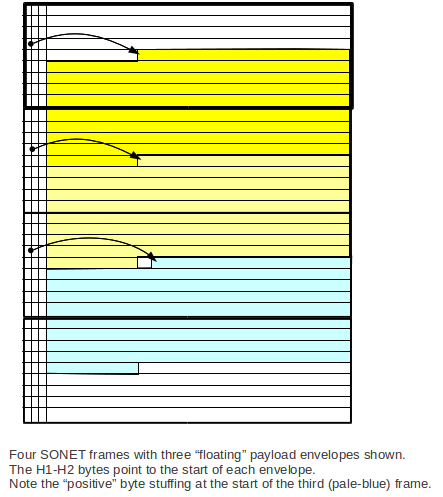
SPEs are generally spread over two consecutive frames. It is often easier to
visualize this if we draw the frames aligned vertically. The "positive byte
stuffing" will be discussed below.
The first column of the SPE is the path
overhead; columns 30 and 59 are also reserved. In the diagram
above, these are the columns beginning with J1. Total data columns: 84. Note
that the path-overhead columns mean that the longest run of bytes before a
1-bit is guaranteed is about 30; the SONET clocking is usually
accurate enough to send 240 0-bits (30 bytes) and not lose count (well,
maybe sometimes accurate enough).
SONET resynchronization
However, sometimes SONET does lose count, and has to re-enter the
"synchronization loop". This can involve a delay of a few hundred frames
(~40-50 ms). Packets with the "wrong" kind of data (resulting in long runs
of 0-bits after scrambling) are often the culprit; carriers don't like this.
Frame synchronization is maintained
by keeping track of the fixed-value framing bytes A1A2. If these are ever
wrong (ie not 0xF628), we go into the resynchronization
loop. Every bit position is checked to see if it begins the 16-bit sequence
0xF628. If it does, we check again one full frame later. Over a certain
number of frames we decide that we are synchronized again if we keep seeing
0xF628 in the A1A2 position.
Note that synchronization involves finding the byte boundaries as well as
the frame boundaries.
0xF628 is 1111 0110 0010 1000. It is straightforward to build a finite-state
machine to recognize a successful match, while receiving bits one at a time.
There is no natural byte framing in SONET. (Actually, there is no natural
byte framing on any synchronous
serial line.)
8000
SONET frames are always sent at 8000 frames/sec (make that 8000.0000
frames/sec). Thus, any single byte position in a frame can serve, over the
sequence of frames, as a DS0 line, and SONET can be viewed as one form of
STDM.
STS-1: 9 rows × 90 columns × 8 bits/byte × 8 frames/ms = 51840 b/ms frame
rate
Data rate: 9 rows × 84 columns × 8 × 8 = 48.384 mbps
DS-3 rate: 44.7 mbps
STS-3: exactly 3 STS-1 frames
An end-to-end SONET connection is essentially a "virtual circuit", where the
sender sends STS-1 frames (or larger) and the receiver receives them. These
frames may be multiplexed with others inside the network. These frames are
themselves often the result of multiplexing DS lines and packet streams.
SONET connections are divided into the following three categories, depending
on length:
- a section is a single run of
fiber between two repeaters.
- a line is a series of
sections between two multiplexers.
- a path is anything longer
Stuffing
The SPE arrival rate can run slower than the 8000 Hz frame rate, or faster.
Stuffing is undertaken only at the Line head, ie the point where
multiplexing of many SPEs onto a single line takes place.
Positive stuffing is used when the
SPEs are arriving too slowly, and so an extra
frame byte will be inserted between occasional SPEs; see the diagram above.
The SPE-start J1 byte will slip towards the end of the frame. Some bits in
the H1-H2 word are flipped to indicate stuffing; as a result, in order to
ensure a sufficient series of unflipped H1-H2 words (for reliable
interpretation of the payload-envelope start), stuffing is allowed to occur
only every third frame.
Negative stuffing is used when the
SPEs are arriving slightly too fast. In this case, the pointer is adjusted
(again with some bits in the H1-H2 word flipped to signal this), and the
extra byte is placed into the H3 byte. The J1 SPE-start byte moves towards
the start of the frame ("forward").
Note that negative stuffing cannot occur twice, but never has to. Stuffing
is only done at line entry. If a line is ended, and demultiplexed, and one
path is then remultiplexed into a new line, then stuffing begins all over
again with a "clean slate".
The fact that the SPE can "slip back" (or creep forward) in the frame means
that once we handle a byte of slip/creep, we're done with it. It doesn't
accumulate, except as an accumulation of slip/creep.
Virtual Tributaries
An STS-1 path can be composed of standard "substreams" called virtual
tributaries. VTs come in 3-column, 4-column, 6-column, and 12-column
versions.
If we multiplex 4 DS-1's into a DS-2, and then 7 DS-2's into a DS-3, then
the only way we can recover one of the DS-1's from the DS-3 is to do full
demultiplexing. Virtual tributaries ensure that we can package a DS-1 into a
SONET STS-1 channel and then pull out (or even replace) that DS-1 without
doing full demultiplexing.
You can lease a whole STS-N link, a SONET virtual tributary, or a DS-1 or
DS-3 line.
SONET and clocking
This is very synchronous.
All clocks trace back to same atomic source. For this reason, clocking is
NOT a major problem. Data is sent NRZ-I, no stuffing.
Strictly speaking, all the SONET equipment in a given "domain" gets its
clock signal from a master source for that domain. All equipment should then
be on the same clock to within ± 1 bit.
The stuffing mechanism described above is for interfaces between
"clock domains", where there may be slight differences in timing. When this
occurs, we are back to a plesiochronous setting.
NOTE: the rectangular layout
guarantees at most 87 bytes before a nonzero value; XOR with a fixed
pseudorandom pattern is also used. (Actually, the max run of 0's is 30
bytes, because of the "fixed" SPE columns.)
SPE path overhead bytes:
J1: over 16 consecutive frames, these contain a 16-byte "stream identifier"
B3: SPE parity
C2: flag for SPE content signaling (technical)
G1: round-trip path monitoring ("path status")
F2: path orderwire
H4:
Z3, Z4, Z5: path data
Note that the J1 "stream identifier" SPE byte is the closest we have to a
"stream address". SONET streams are more like "virtual circuits" than
packets (a lot more like!): senders "sign up" for, say, an STS-1 channel to
some other endpoint, and the SONET system is responsible for making sure
that frames sent into it at the one end come out at the right place at the
other end. Typically the input to an STS-1 channel is a set of DS-1/DS-3
lines (at most one DS-3!), or perhaps those mixed with some ATM traffic.
An orderwire is a circuit used for
management and maintenance. In the SONET orderwire examples below, the
orderwire circuits in the path overhead and transport overhead are DS0,
making them suitable for voice. But there is no requirement that voice
actually be used.
IP over SONET
This can be done IP → ATM → SONET, or else using POS (Packet Over SONET).
The IP packet is encapsulated in an HDLC packet, using HDLC bit stuffing as
needed; we don't care about packet-size expansion because there are no tight
timing constraints on IP packet transmission. We then lay the results out in
the data part of a SONET frame, using the Point-to-Point Protocol (PPP) to
supply signaling overhead. During idle periods, we send the HDLC start/stop
symbol (0111 1110) bytes, which might not in fact end up aligned on byte
boundaries of the SONET frame due to HDLC bit-stuffing. The PPP/HDLC
combination works over any bitstream.
Note that SONET bitstreams do have byte boundaries, but there are no byte
boundaries in the T-carrier hierarchy. (Why do you think SONET bothers with
bytes?) The Packet Over SONET approach simply ignores the underlying SONET
byte boundaries.
Virtual-circuit packet-switched routing
We don't usually use the word "virtual" for TDM, though TDM circuits are in
a sense virtual. But "virtual circuit switching" means using packets
to simulate circuits.
Note that there is a big difference between circuit-switched T-carrier/SONET
and any form of packet-based switching: packets are subject to fill
time. That is, a 1000KB packet takes 125 ms to fill, at 64 Kbps,
and the voice "turnaround time" is twice that. 250 ms is annoyingly large.
When we looked at the SIP phone, we saw RTP packets with 160 B of data,
corresponding to a fill time of 20 ms. ATM (Asynchronous Transfer Mode) uses
48-byte packets, with a fill time of 6 ms.