Comp 353/453: Database Programming, Corboy
523, 7:00 Thursdays
Week 6, Feb 23
Read in Elmasri & Navathe (EN)
- Chapter 3, The Relational Data Model ...., section 3: Update
Operations
- Chapter 4: Basic SQL
- Chapter 5:
Midterm: March 15
Homework 2 updated rules:
Due Sunday, Feb 26, 2012 (was Feb 24)
All submissions must be in text format, WITHOUT UNICODE (especially
unicode quotation marks)! Use only standard ASCII quotation marks ' and
", as needed. Be aware that if you paste your work into a MSWord file,
quotes may be changed to unicode.
All SQL queries should be "copy-and-paste ready"; that is, any
extraneous marks (such as "->" or other prompts) should be edited
out. Leading spaces are ok; however, tabs have strange consequences and
you should try to avoid them.
When a query is requested, your answers should be in the form of a
SINGLE query; do not retrieve a value with one query and then manually
plug that value into a second query.
First look at PHP PDO and LAMP (or WAMP)
Try removing the ";" from the include statement in pdo1.php to admire the elegance and precision of the resultant error message.
A brief word on auto-commit
To commit your SQL updates is to write the changes to the permanent database; in this sense, it is like save. So far we've assumed that there is a commit operation performed after every insert or update; this situation is called auto-commit. Generally, auto-commit mode is an attribute of your database connection; if auto-commit is true then a commit is performed after every SQL statement that potentially alters the database.
The alternative to auto-commit is to execute a group of updates, and then explicitly invoke the commit
operation at the end, to commit all the updates together. A group of
SQL statements between consecutive commits is then called a transaction; all the statements of the transaction are committed
together. Usually, though, we want a stronger assurance: that all the
statements of the transaction either succeed, or none of them do (this
is implicit if we know that commits always succeed, but this is not the case in the real world). This is known as the atomicity
requirement, the first part of the ACID test (atomicity, consistency,
isolation, durability). The idea is that a transaction should be atomic, that is, indivisible: the individual queries that make it up should be executed as a unit.
Instead of a commit, a user may also issue a rollback, which means to throw away all the actions back to the previous commit, thus discarding the transaction.
We'll stick with auto-commit for a while longer, but be aware of two things:
- This is why there is no "save" operation
- auto-commit is not universal; sometimes you need manual control
Entity-Relationship modeling
Here's a summary for the construction of entities:
- Look for the "concrete" objects in the problem domain
- List the attributes of each entity.
- Break compound attributes down into atomic attributes
- Attributes can, at this stage, be multivalued
- Indicate the (single-attribute) key for each entity
- Do not use other
entities as attributes; model this instead at the relation stage
- This may leave some entities ("weak" entities) without a complete
key. Just mark them as such
- Weak entities will be tied to some other entity through the defining relationship.
Relationships
Initially we arrive at Fig 7.8, with four entities: DEPARTMENT,
PROJECT, EMPLOYEE, DEPENDENT. Note that Works_on here is shown as an
EMPLOYEE attribute; it could also be represented as a PROJECT
attribute. How are we representing department membership? Who works on
what? Who is in charge of what projects?
Note some of the attributes in figure 7.8 refer to other entities.
These are our first relationships; these will likely end up translated
into foreign key constraints.
A relationship formally is a
set of ordered tuples ⟨e1,e2,...,en⟩ where each ei is a member of
entity Ei. Some entities here may simply be attributes (eg the hours attribute of the WORKS_ON
relationship ⟨employee,project,hours⟩.
The tuples in a relationship must each have a clear meaning to the
application. Relationship names are usually verbs, and should make
sense "left to right" (and sometimes top to bottom). That is, we would
prefer the relationship name supervises
because it fits in with
SUPERVISOR----- supervises
------EMPLOYEE
We could also use
EMPLOYEE ----- reports_to
------ SUPERVISOR
Most relationships are binary (possibly with added attributes); ternary
and higher-degree relationships are less common.
At this stage, we may model a relationship as a (typically multivalued)
entity attribute; consider again how we modeled WORKS_ON in Figure 7.8.
When a relationship involves multiple entities, we can assign a role name
to each entity. Commonly this is just the name of the entity (eg
EMPLOYEE), but in relationships between an entity and itself (so-called
recursive relationships), we
have to use different names. Consider the example of the SUPERVISES
relationship.
Example: fig 7.11; note that the righthand SUPERVISION
oval contains references to pairs
of entities in the lefthand EMPLOYEE oval.
For entities, it is often the case that we elect to use synthetic keys:
arbitrarily generated "ID numbers". This makes sense for departments
and employees. Relationships, however, typically have a natural key
consisting of one primary key from each entity; using synthetic keys
(eg order numbers) should stand out. A good example of this is the
GRADE_REPORT table, indexed by student_number and section_identifier
(and with attribute grade).
How should we model SECTION in the school database? We did model it as
an entity, but could we model it as a ternary relationship between
course, semester, and instructor? No, if we allow an instructor to
teach two sections of the same course in the same semester.
What about an INVOICE? This consists of a number of ITEMs, each with
quantity, ordered by a single CUSTOMER. We can create a relationship
ORDERS between CUSTOMER and ITEM, but an invoice is more than that. If
a customer places multiple orders on the same day, the customer likely
expects them to remain different. So instead we would have an entity
for INVOICE, with attributes invoice_number (synthetic), and date, and
customer, and then create a relationship ORDERS between INVOICE and
ITEM, with attributes for price and quantity:
invoice
|
item
|
price
|
quantity
|
1002
|
37
|
$5
|
6
|
1002
|
59
|
$3.45
|
2
|
1003
|
101
|
$1300
|
1
|
Cardinality
Binary relationships can be
classified as 1:1, 1:N, N:1, or M:N. In the
WORKS_FOR relationship, between DEPARTMENT and EMPLOYEE, this is 1:N.
Each
employee works for 1 department, but a department can have multiple
employees. (Again, the 1 here in 1:N represents a constraint; the N
represents no constraint. It is not actually required that all
departments have multiple employees.)
The MANAGER relationship is 1:1 (though see the note): every dept
has one manager and vice-versa. This is a 1-1 relationship between
EMPLOYEE and DEPARTMENT. Note that most employees are not managers;
this does not change the fact that no employee manages two departments.
See Fig 7.12 for a diagram representing this.
Note: that the MANAGER relationship is
1:1 expresses a business rule:
no employee manages more than one department, and no department has two
managers. The latter is pretty universal; the former, while common, is
not.
Many relationships are 1:N (one-to-many):
DEPARTMENT ----1--- employs ----N-----
EMPLOYEE (or employee works_for department)
EMPLOYEE -----1----- supervises ----N------EMPLOYEE
(boss is on left side)
DEPARTMENT ----1---- controls-----N------PROJECT
Think of "1 department = N employees"; the 1 goes on the side that the other
entity can have only 1 of. The 1 goes on the "larger" unit: a
department is made of N employees, a boss supervises N employees, a
department controls N projects.
See Fig 7.9.
The supervises relationship is "recursive" (a better word, used in the
UML community, is "reflexive"). See figure 7.11 for a diagram.
The WORKS_ON relationship is M:N.
Similarly, the enroll relationship is M:N
STUDENT -----M----- enrolls ----N----SECTION
A section may have several students; each student may enroll in several
sections.
See fig 7.13.
What do we do if, after we've gotten started, we decide that the location attribute of a DEPARTMENT
should be multi-valued? We can model multi-valued attributes as
relationships instead:
DEPARTMENT ----N----is_located_at-----M----LOCATION
Clearly, we would not want this to be 1:M, which would mean that a
location could be used by only one department. If we do decide that
departments have single locations, we go back to an N:1 relationship:
DEPARTMENT ----N----is_located_at-----1----LOCATION
Participation constraints on relationships
Suppose every employee must work for some department. Then the
WORKS_FOR relationship involves total
participation of the EMPLOYEE entity. The MANAGES relationship
involves partial participation
of the EMPLOYEE entity, at least as far as supervisors are concerned.
We represent total participation by a double line, and partial by a
single line.
Relationships can have attributes; eg hours
of WORKS_ON or grade for the
GRADE_REPORT table.
As was described above, entities usually have a single (possibly
composite) key; entities are often given a synthetic
key (ie an employee_id or student_number). Relationships typically have
a key with as many attributes as the degree of the relationship.
Synthetic keys are often awkward for these.
The key to a relationship should be a composite of the keys to each
entity. Otherwise the relationship is not just about the two entities
involved.
Note that synthetic keys work very well for joins.
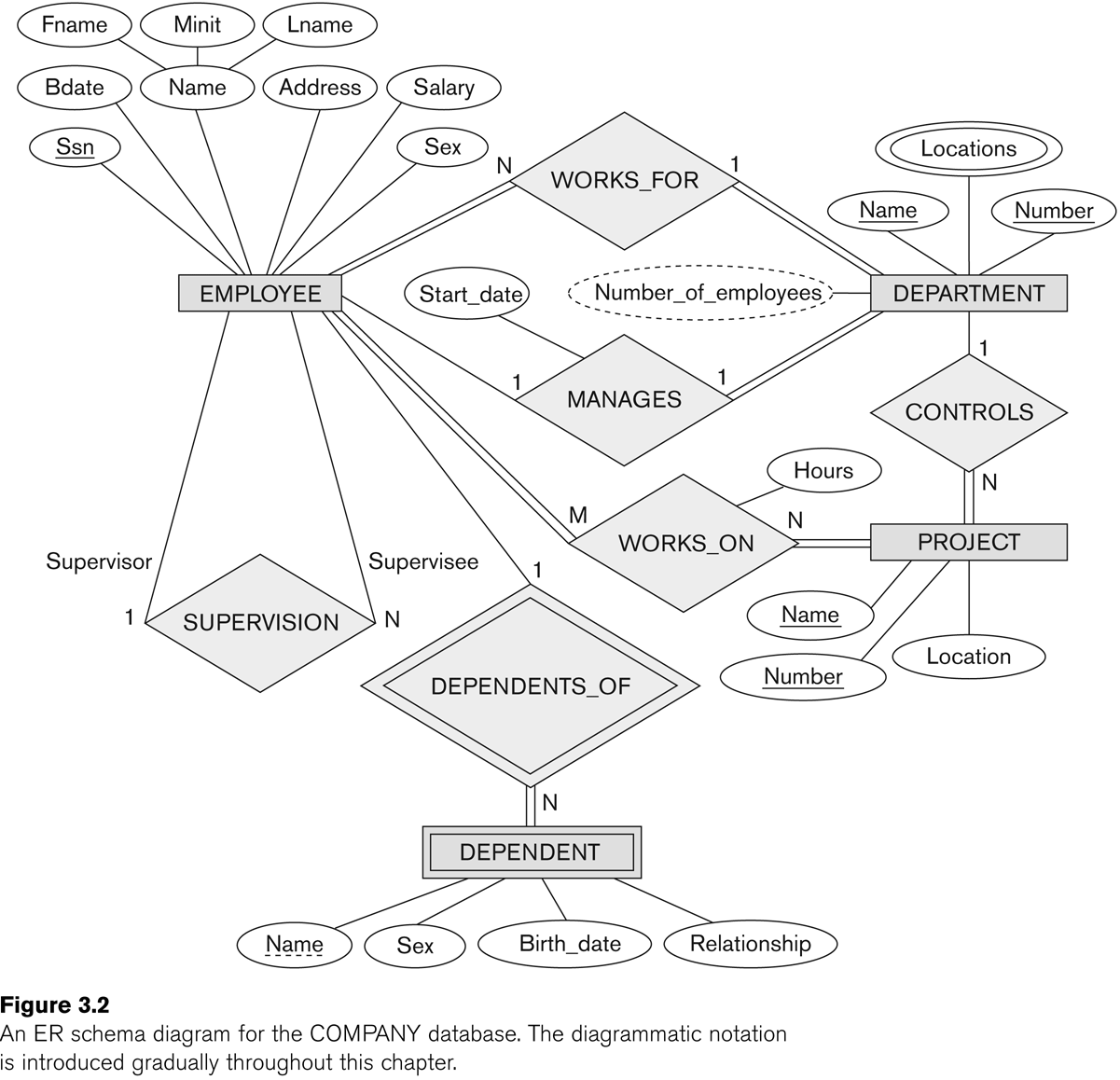
Now we should be able to go through Figure 7.2 (E&N p 204) in
detail. The relationships are supervises, works_for, manages, controls,
works_on, and dependents_of. Note that the name "supervision" is
awkward; it is not clear who is supervising whom. As a result, the
entity links need annotation with the role names "supervisor" and
"supervisee". However, such annotation is often a good idea for clarity.
(The figure below was Fig 3.2 in an earlier edition of E&N; it is
Fig 7.2 in the 6th edition.)
Sometimes, as we rethink things, an attribute can be changed to a
relationship, or vice-versa. Sometimes an attribute may be promoted to
an entity, particularly if it was used in several other entities, in
which case we may also add a
relationship to those other entities.
Relationship attributes can sometimes be moved to entities. For a 1:1
relationship, the relationship attribute can be moved to either entity. For a 1:N
relationship, the relationship attribute can be moved to the N side. Consider the
earlier examples:
DEPARTMENT ----1--- employs ----N-----
EMPLOYEE attribute: start_date, etc
EMPLOYEE -----1----- supervises ----N------EMPLOYEE
attribute: review_date
DEPARTMENT ----1----
controls-----N------PROJECT attribute:
project_budget_num
Sometimes we have entity attributes that need to be translated into
relationships. See Section 7.6. We would move manager information from
the DEPARTMENT entity to the MANAGES relationship. We started out with manager as an attribute of
departments, but later realized that there was a relationship involved
because two entities were
involved: DEPARTMENT and EMPLOYEE. This suggests the need for a
relationship.
We would move controlling-department information from the PROJECT
entity to the CONTROLS relationship. We would remove department,
supervisor, and works_on from EMPLOYEE. Note that some of these will
eventually be added back. At this point, we should have eliminated most
multi-valued attributes.
ER diagram for the STUDENT database
Entities: student, course, section
(min,max) annotation
Instead of labeling lines connecting a relationship to an entity with
1, M, or N, we can also use a (min,max) notation, meaning that each
entity e in the entity set E must participate in at least min entries
of the relationship, and at most max. If min>0, the participation is
total; min=0 means partial participation. The max is denoted N when we
mean it is allowed to be >1.
Note that a 1-N relationship would have the values reversed using the
(min,max) notation:
DEPARTMENT ----1--- employs ----N----- EMPLOYEE
DEPARTMENT ---(1,N)--- employs --- (1,1)-----
EMPLOYEE
Example: Fig 7.15
UML diagrams
See Figure 7.16. UML diagrams have space for operations,which
in the world of databases we're not much concerned about. The big boxes
are for entities; relationships have been reduced to boxes that
annotate links. A (min,max) notation is used, but the label goes on the
opposite entity.
UML relationships (actually, ER relationships as well) may either be of
association or of aggregation. The latter implies a
collection, eg of employees into one department.
How do we translate this to tables?
We'll go into more detail later, but for now, note that a 1:1
relationship can be represented as an attribute of either entity. A 1:N relationship
can be modeled as an attribute of one
of the entities (the entity on the side of the N). M:N relationships
must get their own table.
ER-to-relational mapping
How do we build a database schema from an ER diagram?
Step 1: regular entities
We define a table for each non-weak entity. We use all the leaf
attributes; composite attributes are represented by their ungrouped
components. Keys are also declared. Attributes that were earlier pushed
into relationships are not yet included.
Step 2: weak entities
We create a table for each weak entity, adding the keys for the owner
entity type (or types) (this would mean employee ssn), and adding a foreign key constraint to the owner-entity table.
We are likely to use the CASCADE option for drop/updates: if an
employee ssn is updated, then the dependent essn must be updated, and
if an employee is deleted, then all the dependents are deleted too.
Step 3: binary 1:1 relationships
Let S and T be the participating entities to 1:1 relationship R. We
pick one of the two -- say S -- and add to S a column that represents
the primary key of T, and all the attributes of R.
It is better to choose as S the entity that has total (or at least
closer to total) participation in R. For example, the manages
relationship between departments and employees is 1:1, but is total
only for DEPARTMENT, and is nowhere near total for EMPLOYEE. Thus, we
add a column manager to DEPARTMENT. However, adding a column manages to EMPLOYEE would work.
We also add a foreign key constraint to S, on the new attribute, referring to the primary key of T.
One alternative is to merge S and T into a single relationship; this makes sense only if both have total
participation in R. This means that S and T each have the same number
of records, and each record s in S corresponds to exactly one t in T.
A third alternative is to set up a table R containing <sk,tk> key pairs.
Step 4: binary 1:N relationships
Let us suppose S---N---R---1---T. We now add T's key to S as an attribute with foreign-key constraint. We must add T's key to S; we cannot do it the other way around. In the relationship
DEPARTMENT ----1--- employs ----N----- EMPLOYEE
we would have S be EMPLOYEE; we would put a dno column in EMPLOYEE (why can't we add an essn column to DEPARTMENT?)
An alternative is the <sk,tk> keypair table. This might be more
efficient if only a few s in S participate in the relationship;
otherwise we would have many NULLs in the T-column of S.
Step 5: binary M:N relationships
Here we must create a table R of tuples including the key of S (sk), the key of T (tk), and any attributes of R; we can not
push the data into either S or T. Call the new table also R (note that
E&N call it S). The sk column of R should have a foreign key
constraint referring to the key column of S, and the tk column of R
should similarly have a foreign key constraint to the key column of T.
The WORKS_ON table is a canonical example; so is the GRADE_REPORT table.
Again we would likely to use the CASCADE option for deletion or update of records in the participating entities S & T.
Step 6: multivalued attributes
If we have any left, they must be moved into their own tables. For example, if employees can have several qualifications
(eg degrees or certifications), we would create a table QUALIFICATION
with two columns: essn and qualification. The DEPT_LOCATIONS table is
similar. Again, we would have an appropriate foreign key constraint
back to the original table.
Step 7: higher-degree relationships
These are handled like binary M:N relationships.
More on Foreign Keys
Here's the seven-step ER-to-relation algorithm again, slightly simplified:
- create a table for each regular entity
- create a table for each weak entity, adding the key field from the owner entity as a foreign key for the new entity.
- for binary relationships between entities E1 and E2, pick one of
them (eg E1) and add to it a field conntaining the key to E2. Make this
a foreign key in E1.
- for binary 1:N relationships between E1 and E2,
E1---1---R---N---E2, add a column to E2 containing the key of E1. Make
this a foreign key in E2.
- For binary N:M relationships between E1 and E2, create a new
table R consisting of ⟨E1.key, E2.key, R.attributes⟩. Make E1.key and
E2.key foreign keys in R.
- For multivalued attributes of entity E, create a new relation R.
One column of R will be E.key; this should be a foreign key in R.
- ternary and higher-degree relationships: like step 5.
Joins arise in steps 2, 3, 4, 5, 6, and 7, for recovering the original relationships (or attribute sets for 6, or entities for 2). In every case, the join field is a key of one relation and a foreign key in the other.
Not all joins are about recovering relations from an ER diagram.
Also, I said earlier that entity T should not have an attribute that
was another entity of type S; instead, we should create a relationship
R between T and S. If S was at all a candidate for an attribute,
each T would be related to at most one S and so this would have
cardinality constraint T---N---R---1---S. Then, when we did the above
conversion, in step four we would add S's key to T with a foreign key
constraint referring to S.
But suppose we did add S as an entity attribute to T. Then we would end up with the same situation: we would use the key of S as an attribute of T, and create the same foreign-key constraint. So in the end we get the same thing.