Comp 346/488: Intro to Telecommunications
Tuesdays 7:00-9:30, Lewis Towers 412
Class 14: Dec 7
VOIP & telecom business issues
Clos switches
RSVP and Differentiated Services
Reading (9th edition)
20.1 Integrated Services Architecture (skim)
20.2 Resource Reservation Protocol
20.3 Differentiated Services
VOIP
basic overview of computer-computer, computer-phone, and phone-phone services
packetization issues; compare with ATM
A common packet size for RTCP is 160 bytes, representing a 20 ms fill delay.
On the internet, both delay and jitter are much larger than they are in the voice networks.
Measurement of jitter can vary; two common approaches are the standard deviation in propagation times and the mean deviation in propagation times. The latter involves finding the averate time tmean, and then averaging the absolute values
| tsample - tmean |
The standard deviation approach is appropriate if the delay variation
has a Gaussian (normal curve, or bell-shaped curve) distribution.
Sometimes, however, it does not.
Jain: jitter buffer delay 40-60ms!
Some places refer to jitter up to 100 ms (eg voiptroubleshooter.com)
The basic strategy for dealing with jitter is to introduce a jitter buffer or
playback buffer. However, the typical length of this is 2-4 times the
standard deviation of the propagation time; it is essentially a
worst-case delay response.
Another strategy is an adaptive jitter buffer.
This means that, as the jitter levels rise and fall throughout the
call, the jitter buffer length can change. Increasing it is easy;
decreasing it is hard. However, in many cases we only need to let it
increase, in the event that jitter is worse than expected.
Asterisk.org
vonage-style service
VOIP with commodity QoS versus VOIP with guaranteed QoS.
regulatory issues: in many countries, telephone service is a gov't monopoly.
Interconnection with PSTN
It is trivial to create a single VOIP-to-PSTN relay.
The trickier part is making sure that the internet carries each call as
far as possible. Let Alice be a VOIP user, and let Bob have a
conventional PSTN phone. If Alice calls Bob, we want to route the call
to a voip-to-pstn relay as close to Bob as possible, so that it is a
local call. Similarly, if Bob is to call Alice, we want Bob's local
telephone company to connect to the relay that is as near to them as
possible.
The end result of this is that, if the VOIP network is reasonably sized, every call involving the PSTN is seen by the PSTN as a local call (intraLATA call), subject to minimal billing.
Another way to put this is that the VOIP network needs to be an IntereXchange Carrier, or IXC, ie a long-distance provider.
Do we need VOIP-to-PSTN relays? Skype manages quite well without, and
there are even SIP phone networks that do not connect to the PSTN.
Someone at home can accept a skype call on their computer almost as
easily as answering a landline phone. It's hard, though, to argue that
we don't need to reach cellphone users.
In the US, the country is divided into LATAs, or Local Access and
Transport Areas. These were originally defined in the AT&T
divestiture judgment of 1984, separating AT&T from the seven "baby
bells" (Regional Bell operating company, or RBOC). LATA boundaries are
now determined by the FCC. Since then, new US LATAs have been created,
and Canada has adopted the LATA structure.
Map: http://upload.wikimedia.org/wikipedia/commons/1/1f/LATAs.png
You want your VOIP call to terminate in the same LATA, and probably the
same state; there is some confusion about calls in the following
categories:
- made within one LATA but to another state,
- made within one state but to another LATA
The latter category, especially, confuses the heck out of people.
Also, it is common for intraLATA (within one LATA) calls to be billed at a higher rate than interLATA calls. This has to do with competition.
A LATA is a tariff region; the actual carrier (which may not be related
to the original RBOCs) is your Local Exchange Carrier, or LEC. Verizon,
for example, is still a LEC in some markets. Frontier Communications is
another (currently buying many Verizon subscribers). Non-RBOC LECS are
sometimes called Independent Exchange Carriers, or IECs. (This is not
to be confused with ILECs, or Incumbent LECs, the phone company with the "natural monopoly" in a given region; competitive LECs or CLECs are the johnny-come-lately alternative providers.)
Note that another notion of local calls
may be defined by your LEC to be calls of very short distance (commonly
~8 miles), and not subject to per-minute billing at all.
SS7 and switching between LECs
The basic infrastructure owned by a given company is a set of DS0 trunk
lines. One company can route a call internally, by assigning it a trunk
along each path, and setting up the necessary switching.
Signaling System 7 is used between phone switches, both within a
company (to do the above setup) and also between companies. In the
latter setting, some of its capabilities include
- I am forwarding to you a call placed from 212-555-1234 to 312-555-5678. It will be on trunk 067
- may be sent to the final LEC
- may be sent by the originating LEC to a long-distance provider
- Someone just dialed 800-555-1212. How do I route this?
- The party called for the call on trunk 1035 is busy. Please let the caller know, and release the trunk.
- The route to Adamant is congested. Avoid sending calls there, unless they are high-priority.
- Trunk 068 has been removed for service
LECs use SS7 to get their T-carrier/SONET lines to work with others.
CallerID spoofing
Generally, you cannot set the number to be
sent as your CallerID
(CID) string. However, this is possible if you have a (possibly
fractional) T1
connection, also known as a PRI (Primary Rate Interface) line (this
includes ISDN connections, which can be as little as two DS0 lines plus
an 8kbps signaling channel). Asterisk
allows you to specify the CID string, but it will not be passed along
to the telco central office if you use analog (FXS/FXO) communication.
In general, FXS/FXO (dialtone)
signaling is very primitive compared to PRI signaling. Another example
is handling Direct Inward Dialing. If you have a small number of
FXS/FXO trunk lines to your phone switch, and rather more internal
extensions, then when an incoming call arrives the switch must figure
out to which extension it is to be connected. Theusual strategy was Direct Inward Dialing (DID),
in which the telco would transmit the last four (typically) digits of
the destination phone number (probably by touchtone signaling), when
the inbound call arrived. Normally, inbound calling is handled by
activating the ringer, and waiting for the phone to go "off-hook";
there is plenty of idle time for the DID signalingdigits.
Because of the possibility that the CID string is not generated by
the telecom provider, CallerID is not as secure as an actual line
"trace". This
is not likely to change, because there are many examples of legitimate
CID spoofing:
- Answering services, that want forwarded calls to appear as if they came from the original party
- calling-card companies, that want calls to appear as if they came from the calling party
- businesses that want the central number to appear, or that want
the employee desk number to appear when the employee dials from a cell
phone
- google-talk, which sends its own number
Every line has an associated ANI (Automatic Number Identification) that
refers to the actual billing number. 800-numbers get your ANI when you
call them, even if you block CallerID.
SIP/SDP & H.323
These are all forms of session-setup protocols; the actual data
transfer would then be handled via RTP or the equivalent (below). SIP
& SDP are IETF protocols; H.323 is standardized by the
International Telecommunications Union. Within the TCP/IP world, this
means that there tends to be a bias in favor of SIP. H.323 may provide more complete switching options.
SIP (Session Initiation Protocol) can be used to set up two-party
calls, or multi-party calls, or teleconferencing. It can also be used
for game setup, or for instant messaging. It is somewhat similar in
message format to HTTP. It is often used in conjunction with the
Session Description Protocol, SDP; the SDP data defines the format of
the proposed call and is typically encapsulated in the SIP packet. SDP
allows specification of IP addresses, names, and specific formats for
the data streams. SIP can interact with Signaling System 7, though the
two are structurally rather different.
SIP can be used to get two Asterisk servers to communicate, though it is more common to use IAX for that.
Goals for SIP include:
- locating the correct remote endpoint (sometimes this amounts to a form of paging)
- determining whether the user is available
- coordinating the audio/video encoding mechanisms
- setting up the RTP session, including specification of port numbers
- managing the ongoing session, including teardown at the end
Often the initial connection to a user is made to a sip proxy;
the asterisk server acts as a proxy for the cisco phones. If your
phones are behind a NAT firewall, you will need a proxy outside.
Proxies forward on SIP packets, perhaps after editing them; proxies may
negotiate a more direct route for the actual call path. Proxies
typically know the locations of the various local telephones; there is
a SIP registration mechanism for a phone to announce itself to, say, its Asterisk server. A proxy may also fork a call to multiple devices (eg to my desk phone and my cell phone); forking may be parallel or sequential.
SIP endpoints are User Agents, or UAs. Other entities are
- Registrar Servers: databases containing information about all UAs
that have registered with that server. The Asterisk box was a registrar
server
- Proxy servers: these accept SIP connections from UAs or other proxies, and using information from a Registrar Server they will forward the connection to the destination UA or to another intermediate proxy. Proxy servers can be stateful (meaning they retain call information) or stateless (meaning they do not, though they do remain in the initial setup path, unlike redirect servers).
- Redirect Servers: these are proxy servers that return messages such as Moved Temporarily; the previous proxy then continues building the proxy chain.
Connections start with a sip URI (uniform resource identifier -- not locator!), eg
SIP:pld@cs.luc.edu or SIP:
Someone calling me would start with an INVITE message, sent by their
proxy (the User Agent Client, or UAC) to mine. My proxy may not be the
final stage, however. As the INVITE message is passed along, each proxy
returns the message 100 Trying. Eventually the INVITE reaches the end of the path (or fails), and the phone rings. It also sends back 180 Ringing. When the phone is answered, it sends back 200 OK
along the proxy chain. Sometimes there are SIP proxies ("stateless"
proxies) that lie between proxyA and proxyB on the path, but which
"edit themselves out" of the final signaling path.
One of the purposes of the proxies is to allow connection to sip:pld@cs.luc.edu through any of several phones, thus supporting forwarding: my office phone first, but my cell phone if I have pressed a button on my office phone to forward calls.
The actual data (the RTP packets) do not traverse the proxy path; they
take the most direct route they can. Note, however, that endpoints
behind NAT firewalls will need some kind of proxy.
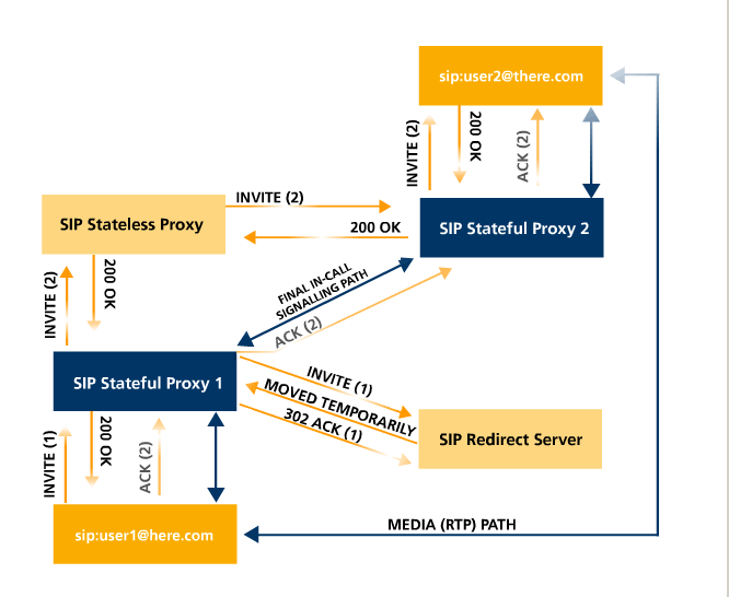
In the above picture (from http://en.wikipedia.org/wiki/File:SIP_signaling.png), the following has happened:
- user1 sent INVITE(1) to Proxy1
- Proxy1 sent INVITE(1) to the Redirect Server, which responds with MOVED TEMPORARILY
- Proxy1 then sent a new INVITE, INVITE(2), to the Stateless Proxy
- INVITE(2) is forwarded to Proxy2
- Proxy2 forwards it to user2
- User2 sends back 200 OK, which traverses Proxy 2, Stateless Proxy, and Proxy 1
- User1 then sends ACK(2), which bypasses the Stateless Proxy (no longer in the "path")
One advantage of SIP, as a protocol, is its greater flexibility. New
data formats can be added to SDP very quickly; getting revisions to
H.323 can take decades and usually takes years.
H.323
This is rather like SIP, except everything has a different name. (To be
fair, there are also additional features). Proxy servers are known as Gatekeepers or Peer Elements or Border Elements. H.323 has more features for admission control and authentication.
Where SIP connections begin with an INVITE message, H.323 may (this is
what the telecom world is like) begin with a Request for Permission To
Call.
See http://en.wikipedia.org/wiki/H.323.
RTP & RTCP
RTP is Realtime Transport Protocol, a generic UDP-based way of sending
"realtime" (audio and video) data. The RTP header contains:
- 9 bits of general identification information
- 7-bit payload type
- 16-bit sequence number (for reordering)
- 32-bit timestamp
- one 32-bit SSRC (Synchronization Source) identifier (identifying the sender)
- a variable number of CSRC (Contributing Source) identifiers (identifying logically significant substreams of the SSRC).
Examples of CSRCs might be the separate video and audio feeds, or
synchronized video feeds from multiple locations or cameras, or
synchronized feeds from multiple microphones.
We earlier looked at some of the RTP packets from a call placed by the
cisco VoIP phone. These packets were 214 bytes, consisting of
- 14-byte Ethernet header
- 20-byte IP header
- 8-byte UDP header
- 12-byte RTP header
- 160 bytes of data (20 ms at 64kbps)
Because the RTP header was only 12 bytes, there were no CSRCs, which is
what we would expect for a single voice channel. The RTP payload type
was 0x00, which is desigated as ITU-T G.711 PCMU, which is µ-law/A-law logarithmic companding of 8-bit PCM audio with a sampling rate of 8000.
Other payload-type codes may be found in RFC 3551, page 33 (RTP A/V Profile).
RTP timestamps are provided by the sending application,
and are application-specific. Their primary purpose is to synchronize
playback. For the cisco phone, the timestamps were in multiples of 160,
starting at 160; these would represent the number of "sampling ticks"
(at the rate of 8000/sec) up to the end of the current data.
RTP packets are generated only by the sender; the flow is one-way. The
RTP protocol does not include any form of acknowledgement. However,
associated with RTP is the Realtime Transport Control Protocol
(sometimes called RTP Control Protocol), or RTCP.
This has several goals, in each direction; one goal is to support
tagging of RTP streams, and to support coordination and mixing of RTP
streams that have not been mixed ath the SSRC/CSRC level. However, for
our purposes the primary goal of RTCP is to provide acknowledgment-like
feedback from receiver to sender, indicating the packet loss rate. Here
is that portion of the data from one of the cisco RTCP Receiver Report (RR) packets:
- SSRC contents
- Cumulative number of packets lost: 0
- Extended highest sequence number received: 13322
- Sequence number cycles count: 0
- Highest sequence number received: 13322
- Interarrival jitter: 4
- Last SR timestamp: 0 (0x00000000)
- Delay since last SR timestamp: 4294710854 (65532087 milliseconds)
RTP applications can elect to
receive this information (in particular, the fraction lost), and adjust
their sending rates (eg by choosing a different encoding) appropriately.
There is a Java interface to RTP, java.net.rtp (not
part of the standard Oracle/Sun library). In this package, an
application that wishes to receive RTCP information can create an
RTCP_actionListener, which is invoked asynchronously whenever RTCP
packets arrive, much like a mouse Listener. A standard GUI interface,
however, may consist of essentially nothing but various asynchronous
Listeners. A typical RTP program, on the other hand, will have at least
one main thread involved in the transfer of data, and which will
receive some form of messages or notification (perhaps by setting
shared variables) from the RTCP_actionListener.
Clos switches
We looked at these earlier. Here's the general idea. The concept itself
was first described in a 1953 Bell Labs paper by Charles Clos. The
general idea is the three-column "sparse crossbar":
Column 1: r many n×m crossbars. Total inputs: rn; total outputs: rm
Column 2: m many r×r crossbars. Total inputs: rm; total outputs: rm
Column 3: same as Column 1, reversed (that is, r many m×n crossbars).
The m outputs of each Column 1 n×m crossbar are connected to every one of the r×r Column 2 crossbars.
Any connection is uniquely determined by its entry port (which port on
which Column 1 crossbar), its Column 2 crossbar, and its egress port.
Note that the specific port on the Column 2 crossbar is uniquely
determined by the wiring; we do not have to specify it.
Earlier we considered the case where m=2 (stallings fig 9e:10.6)
All this replaces one large N×N crossbar, where N=nr.
Suppose we take n≃m≃r. Then n ≃ N1/2. The size of the Clos configuration is = 2nmr + nr2 ≃ 3n3 ≃ 3N3/2. The savings in space over the full crossbar is N1/2/3. For N=1000 this is a factor of 10; for N=10,000 it is a factor of 30.
Fact 1: if m ≥ 2n−1, then the switch is completely nonblocking: any
free input on the left can be connected to any free output on the right.
Proof: Here's the simpler case where m=2n−1; the general case is the same, but you use inequalities.
Consider the left and right-hand n×m and m×n crossbars that we wish to
connect: these are the entry and egress crossbars. Each has at most n−1
active inputs, and thus at most n−1 active outputs, and thus at least
m−(n−1) free outputs. The hypothesis means m−(n−1) = m−n+1 = 2n−1−n+1 = n, so there are at least n free outputs.
The entry crossbar thus has at least n free connections to column 2,
and there are similarly n free connections from column 2 to the egress
crossbar. We need to show that there is at least one column 2 crossbar
has a free connection to both
the entry and egress crossbars. But this has to happen, because there
are m = 2n−1 column 2 crossbars, and n connected to the entry crossbar
and n connected to the egress. If there were no overlap in the set of
column-2 crossbars connected to the entry and the set of column-2
crossbars connected to the egress, then there would have to be at east
2n column-2 crossbars in all, which there are not.
Fact 2: if m≥n, then any input can be connected to any output provided
that we are allowed to reroute some existing connections to a different
Column-2 crossbar to make room. Note that all we have to specify for an
existing connection is which Column-2 crossbar it is to use.
Example 1: Nine 3×3 crossbars arranged in a 3x3 pattern. There are
three existing connections, designated by which crossbar in column 1
connects to which crossbar in column 3 (actual ports don't matter). Let
us refer to the middle column crossbars as M1, M2, and M3.
- row 1 to row 2, via M1
- row 2 to row 1, via M2
- row 3 to row 1, via M3
We now wish to add one new connection from row 1 to row 1; this should
be doable, as the row 1 column 1 switch has one of its three inputs in
use, and the row 1 column three switch has two of its three outputs in
use.
However, we cannot use any of the column 2 switches to complete the
circuit: for M1, the line to the entry switch is blocked, and for M2
and M3, the line to the egress switch is blocked.
The call becomes possible if we move connection 1 so that it uses M2,
freeing M1 for the new connection. Or we can move connection 2 so that
it uses M1, freeing M2 for the new connection.
Example 2: see http://en.wikipedia.org/wiki/Nonblocking_minimal_spanning_switch,
"Example of rerouting a switch".
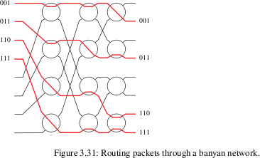
Banyan switches
Banyan switches can replace a full N×N crossbar with N/2*log(N)
switches, arranged in (N/2) rows and log(N) columns. Each input,
however, must be prefixed with a binary routing string
(of length log(N)) representing the output port. Each switch element
has two inputs and two outputs. The element uses the first bit of the
prefixed routing string to decide which output to use.
Banyan networks many involve collisions, in principle. In practice, a
mesh can be constructed so that collisions never occur, so long as the
inputs that enter the switch fabric simultaneously are sorted by their routing strings: eg 001, 101, 110, 111.
RSVP / Integrated Services; Stallings ch 19.3
First point is that even without real-time traffic, we'd probably
like to prioritize telnet/ssh traffic to avoid queuing problems.
Example of telnet + file download through a slow link.
Simple case with all non-realtime traffic
Realtime traffic: may need throughput, delay, jitter, loss bounds
Notion of "flows": common user, endpoints, QoS needs
Problem with the Internet
The situation:
1. IP routers are stateless; that is, they use datagram routing.
THE
biggest argument in favor of ATM, by ATM proponents, was that virtual
circuits allowed routers to know about connections and thus reserve
capacity. How can a datagram router reserve anything?
Routers are subject to being rebooted; hosts may then not be able to
tear down a connection (what if an intermediate router fails!). If
routers have HARD reservation state, they MUST not lose it when
rebooting, and MUST receive teardown notification.
The RSVP solution: "soft state" that times out.
2. Not all routers may start providing RSVP services at once!
3. We need to support "all" known major needs for QoS. Voice is one,
but the other BIGGIE is multicast video/audio for teleconferencing.
Unicast video is also supported, but MULTICASTing is technically much
more complicated to integrate.
Overview of muticasting
Typical model: many more receivers than senders (though teleconferencing may involve lots of people sending, in turn)
Construction of multicast tree: also maintained through soft state.
Multicast also has major "rollout" problems, although one way that has
been addressed is through tunneling (== manual tree construction)
We need to avoid IPv4 fragmentation, so that receivers can identify packets by flow info
"soft state"; times out if not refreshed
requested by receiver (though reservation is for data sent by sender)
reserve in terms of delay and rate/burst
Basic Ethernet version of multicast: using multicast Ethernet addresses
IP: goal is to construct a "spanning tree"
Draw picture.
Compare to "multiple unicast"
A receiver R wishing to join the tree send JOIN messages to the sender
S. However, the routers through which the JOIN message passes on the
way from R to S may have nothing to do with the routers on the path
from S to R. S then sends R's identity out towards R; routers forward
it along the S-to-R path but take no action unless there is a need to
create a new branch.
In some cases, sender doesn't even necessarily know who the receivers are! Receivers just contact routers.
Shortest-Path broadcast:
sender S sends, routers retransmit on all links if packet arrived directly from S; that is, arrived via shortest path to S.
Shortest-Path multicast: routers with no members of multicast group G send this info to neighbors.
Kind of expen$ive.
IP addrs for multicast group: 224.x.y.z ... 239.x.y.z
reverse path problem: figure out how to get back to sender along the path the sender will use to send.
why it is there
Integrated Services Architecture service categories:
-
Guaranteed, (hard delay bound)
-
Controlled load (bandwidth guarantee, loss rates, soft delay bound)
-
Best effort
Within each category, a sender negotiates a "TSpec", somewhat like GCRA specs.
Fig 9e:20.3 / 8e:19.11: good picture of Token Bucket
Note that to get guaranteed performance, we need ALL routers on the
path to use the algorithm. How do we roll out service incrementally?
Categories (Stallings, p 632, 8th ed)
Guaranteed service:
- guaranteed throughput
- bounded queuing delay
- no queuing losses
Controlled-load
approximates best-effort service on lightly loaded networks
- specified throughput
- no uniform bound on queuing delay, but there is a good bound for "most" packets
- queuing losses are very low
Good for ADAPTIVE applications. Voice & video can be made adaptive. (Discuss how.)
Routers typically do weighted fair queuing on whole service categories, not per-flow!
RSVP
RSVP: reservations compatible with multicast: receiver-initiated!!
-
transparent to senders
-
suitable for multicast receivers!!!
-
mechanisms for CHANGES IN ROUTE
Different receivers may have different needs; these can sometimes be accommodated by routers, without bothering the sender.
how RSVP routers recognize flows; IP6 flowID
typical reservation timeout: 30 sec
RSVP does include teardown messages (both directions), but RSVP won't fall apart if they are not sent.
RSVP is transparent to nonparticipating ISPs
Receivers send periodic (30 sec) RESV messages to refresh routers;
routers forward these "up the path". Note that the receiver sends these
to the router from which it is receiving the reserved flow.
- works well if receiver crashes
- works well if router crashes
- how does it figure the path? Because routers send PATH mesg.
Each RSVP sender host transmits RSVP "Path" messages downstream along
the uni-/multicast routes provided by the routing protocol(s),
following the paths of the data. These Path messages store "path
state" in each node along the way. This path state includes at
least the unicast IP address of the previous hop node, which is used to
route the Resv messages hop-by-hop in the reverse direction.
Sometimes RESV messages can be merged!
Sender sends its TSpec in PATH mesg; note that some receivers may ask for a different TSpec
Unidirectional reservations and different paths each direction
R1-----R2
/ \
A--R0 R5---B
\ /
R3-----R4
What if A->R0->R1->R2->R5->B and B->R5->R4->R3->R0->A, with A as sender.
B sends RESV message R5->R2->R1->R0->A by virtue of saved state at routers
But the actual R5->R2, R2->R1 might actually travel R4->R3->R0!
one-pass upstream request means receiver might not even find out what reservation was actually accepted! Though the sender should know....
Initiated by requests sent by receiver to sender; sender sends PATH
packets back down to receiver; these lay groundwork for return-path
computation. The PATH message also contains sender's traffic
specification, or Tspec.
RFC2210: standard Tspec has
- token bucket rate
- token bucket size
- peak data rate
- minimum policed unit m
- max packet size M
NO MaxDelay!!! But see notes in rfc 2212:
applications can use the Tspec values
above to estimate their queuing delay, which when added to propagation
delay gives an accurate total.
How we might do RSVP over the backbone: see notes in rfc2208. Basic idea: do something else there!!
How VOIP may facilitate adoption of RSVP (well, probably not)
merging of multicast reservations
Reasons for lower QoS on some paths:
- lower QoS toleration/affordability
- stepped-down bandwidth
- subscription to only selective "channels"
MaxDelay QoS only: some receivers may accept larger buffer!!!
link-level cooperation with ATM links
One potential advantage over ATM: QoS can change dynamically (this is relevant for video). Also RSVP supports multicast.
Admission control:
how exercised???
ISA diagram: fig 8e:19.10, 9e:20.1
Differentiated Services
Problem: Integrated Services may not scale well. Few ISPs have adopted it. Can we come up with a simpler mechanism?
Differentiated Services: two-tier model. Priority traffic is very limited in bandwidth.
A simple priority queue mechanism to handle the service classes is enough.
scaling issues of RSVP; possibility of use of IntServ in core and RSVP at edges
DS may start with a Service Level Agreement (SLA) with your ISP,
that defines just what traffic (eg VOIP) will get what service. No need
to change applications.
DS octet will be added by ISP.
IP Header: fig 8e:18.6 / 9e:18.5
DS field: fig 8e:19.13 / 9e:20.8: DS values, drop precedence
What happens when your traffic must be carried by another ISP?
What happens if you send more than you've contracted for?
Uses IP4 TOS field (renamed DS), widely ignored in the past.
Routers SHOULD implement priority queues for service categories
Basic idea: get your traffic marked for the appropriate class. Then what?
000 000: current best-effort status
xxx 000: traditional IPv4 precedence
PHBs (Per-Hop Behaviors): implemented by all routers
Only "boundary" routers do traffic
policing/shaping/classifying/re-marking to manage categories
(re-marking is really part of shaping/policing)
EF: Expedited Forwarding
basically just higher-priority. Packets should experience lowest queuing delay.
Maybe not exactly; we may give bulk traffic some guaranteed share
Functionality depends on ensuring that there is not too much EF traffic.
Basically, we control at the boundary the total volume of EF traffic
(eg to a level that cannot saturate the slowest link), so that we have
plenty of capacity for EF traffic. THen we just handle it at a higher
priority.
This is the best service.
AF: Assured Forwarding
Simpler than EF, but no guarantee. Traffic totals can be higher.
There is an easy way to send more traffic: it is just marked as "out".
In-out marking: each packet is marked "in" or "out" by the policer.
Actually, we have three precedence levels to use for marking.
From RFC2597:
The drop precedence level of a packet
could be assigned, for example, by using a leaky bucket traffic
policer, which has as its parameters a rate and a size, which is the
sum of two burst values: a committed burst size and an excess burst
size. A packet is assigned low drop precedence if the number of
tokens in the bucket is greater than the excess burst size [ie bucket
is full], medium drop precedence if the number of tokens in the
bucket is greater than zero, but at most the excess burst size, and
high drop precedence if the bucket is empty.
RIO: RED with In/Out: RED = Random Early Detection
Routers do not reorder!
Fig fig 8e:19.13 / 9e:20.8 and # of classes, drop precedence
4 classes x 3 drop priorities
Error-correcting codes (not on the final)
1. Triple-bit voting: send 111 for 1, 000 for 0. Very inefficient!
2. Example 6.9 in Stallings 8th edition (not, alas, in 7th):
data codeword
00 00000
01 00111
10 11001
11 11110
Notion of Hamming distance.
3. 2-D parity
4. Hamming code (used for error-correcting ram, etc)
8 data bits, 4 check bits
16 data bits, 5 check bits
2^n data bits, n+1 check bits
10101101 data
1 1 1 0 |1 parity of bits with last bit (0th bit) of position = 0
10 11 |1 parity of bits with 1th bit of position = 0
1010 |0 parity of first half
10101101|1 parity of entire thing
Verify we can recover from any 1-bit error in the data
What happens if the second parity bit is a 0?
Reed-Solomon codes (used on CDs, DVDs, etc) (NOT DISCUSSED)
Given k data values (eg k=223), send n>k transmitted values as follows.
Let k data values be a[0]...a[k-1].
Form the polynomial P(X) = a[0] + a[1]X + a[2]X2 + ... + a[k-1]Xk-1
Evaluate P at points x0...x(n-1), and send those values.
Use a "finite field" so there's no roundoff.
Each field value (xi or ai) is a multi-bit symbol.
Max correction: (n-k)/2, which is pretty good. n-k = # of extra bits.
RS works well for burst errors (hence CDs/DVDs); not as efficient as others for single-bit errors