Call Setup and Switching
Peter Dordal, Loyola University CS Department
Call Setup
Revisit Stallings figure 10.2, on plugboard switching. But now envision the
switches as electronic, and the trunk lines as bundles of STDM channels (DS
or SONET) rather than copper wires.

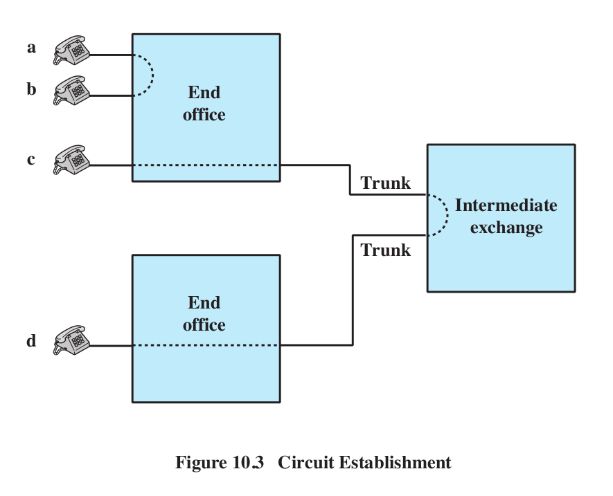
Fig 10.3 shows a simple call setup between nearby offices.
Another switch picture can be found in Fig 10.4. The "Full-duplex lines to
attached devices" at the left should be thought of as channels (including
lines to subscriber equipment). The idea here is to represent the innards of
a single digital switch.

Signaling Types
Between the customer premise and the local office, in-band
(or inchannel) signaling is likely
used: the voice line carries the pulse or DTMF (touch-tone) signals. There
is in most cases no alternative signaling path!
Between offices it is a different story. Once upon a time, in-band signaling
was once used there too. This meant that as each channel in the
end-user-to-end-user path was allocated, the setup signaling would traverse
that path to the next switch in the system; the call-setup signaling
followed the same path through the network as the voice data to come.
Another term for having the signal follow the same path as the data is associated signaling: the signal path is
associated with (that is, identical
to!) the data path. Associated signaling, though, also includes having a
dedicated, digital channel for switch-to-switch signaling; this is sometimes
called out-of-band signaling but that term is also used for something else.
In-band signaling means that the voice path is always used.
Associated signaling (in-band or not) has drawbacks. For one thing, it is
slow, and there can be no global allocation of the channels that make up the
end-user-to-end-user path. The SS7 (Signaling System 7) system, therefore,
allows common-channel signaling
("common" here means that the signaling packets all use one separate
channel/network in common, not in
common with the voice circuits): all the switches are connected via a
packet-switched channel or network that is logically separate from any of
the channels that link adjacent switches. This allows communication between
the endpoints to begin even before any channels are allocated; it also
allows a global channel-allocation strategy. Common-channel signaling is
also, confusingly, called out-of-band signaling.
Out-of-band signaling can, as stated above, be associated, if the signaling
data follows more-or-less the same path as the voice circuits. More likely,
if SS7 or other newer systems are used, the signaling is disassociated,
meaning that unrelated paths are used. Sometimes the term information
plane is used to describe the network map that the voice channels
use; the control plane is the map
of the signaling network.
Blue boxes and in-band signaling
It turns out there was another problem with in-band signaling: it was
vulnerable to hacking.
In the days before SS7, switch signaling was done over the same voice lines
that the call would eventually use. Idle trunk lines would have a 2600 Hz
tone transmitted both ways. Trunk links were allocated to a call on a
hop-by-hop basis starting from the caller: each switch would (a) stop
sending the 2600 Hz tone, and (b) transmit the dialed number as a sequence
of DTMF (touchtone) digits. The receiving switch would save the digits,
allocate a trunk line to be the next link on the path, and repeat the
process. The final switch would simply complete the call to the destination
subscriber using that subscriber's "local loop". The first switch on the
path would be responsible for billing. To tear down the call, the first
switch would send the 2600-Hz tone again to tell the trunk segments they
were idle.
Normally the 2600 Hz tone was generated by the switching office. But there
was nothing to prevent users from generating this themselves. If you did
send a 2600 Hz tone down the line, your call would appear to go "dead" as
the trunk lines were deallocated from your call.
Joe "The Whistler"
Engressia was born blind in 1949, with perfect pitch. He discovered
(apparently as a child) that, once a call was connected, if you sent a 2600
Hz tone down the line, the phone system would now let you dial a new
call, using DTMF signaling, while continuing to bill you for the old
one.
If you wanted to do this to avoid long-distance charges ($1.00/minute in
that era), typically the first call would be local, thus allowing a
long-distance call for the price (often zero) of a local call. Engressia
could whistle the 2600 Hz tone.
According to the wikipedia article on John
Draper, Engressia also discovered that the free whistle in "Cap'n
Crunch" cereal could be modified to produce the tone; Engressia shared this
with Draper who popularized it. Draper took the nickname "Cap'n Crunch".
Draper later developed the "blue box" that would generate the 2600 Hz
trunk-line-idle tone and also other tones necessary for dialing.
So, to place a call, you first needed to dial a local
number: one that would involve at
least one trunk segment, and which was cheap (ie either semi-local
(but still involving one trunk segment), or an 800-number). Billing would
commence at that rate. You then sent the 2600-Hz tone, which would make all
the trunk segments go idle. The first switch, however, not having been
informed of any disconnection, still had you connected to the first trunk on
the path, which we will call trunk1. All subsequent trunk segments would
actually be released.
You would then send the long-distance number, in DTMF form. The trunk1
segment would get these digits and assume they were part of legitimate
call-routing; the call-setup process would run as normal. Note that a real call to that long-distance number
might not use the trunk1 link at all, but that it did not matter.
At this point you were connected to the long-distance number, but paying for
the local number.
This is not the only disadvantage to in-band signaling; another was that the
path had to be allocated on a purely hop-by-hop basis. And the security hole
might have been closeable by other means. Still, the blue-box problem was a
significant one.
Overview of circuit-setup process
Connections are made between A and a, B and B, etc. Trunk lines
-- links between adjacent switches --are really large bundles of "bearer
circuits" (or just "circuits"), ie DS0 channels.
S1[A,B]
\
\
\
S3[]
------------------------------------ S4[]
------------------------------- S5[b,c,d,e,f]
/
/
/
/
/
/
S2[C,D]
S6[E,F,a]
For each switch, the endpoints directly connected to it are in brackets: A-F
connected respectively to a-f. The S3-S4 and S4-S5 links are second-level
multiplexes. We demultiplex at S3, S4, and S5, and a given channel
from the S3-S4 line is connected to a different channel on the S4-S5 line.
Those channel connections are what the circuit setup process must create.
Circuits may be on-demand, as in
phone calls, or permanent, as in
something a subscriber (eg an ISP) has contracted for on a permanent basis.
Circuit-setup can take inefficient paths, causing early
blocking. Consider the following diagram of endpoints A and B and
switches S1 and S2.
        A
      //  \
     //    \
    S1-----S2
     \\    /
      \\  /
        B
This arrangement can support three paths from A to B: two taking the route
A-S1-B and one taking the route A-S2-B. But suppose we create a path
A-S1-S2-B, outlined in red above. Ath this point, only one more path from A
to B is possible (the blue one). The red zigzag path has blocked the third
path.
Trunk Reservation
The problem of allocating trunk channels to a call is known as the trunk
reservation problem.
The simplest strategy is to model trunk reservation after datagram
routing, in which each switch maintains a forwarding
table of ⟨destination,next_hop⟩ pairs. In the case of trunk
allocation, the destinations might be area codes (at least until the
destination area code is reached). A switch S1 would receive a message from
a neighboring switch S2 that a call was to be routed to destination area
code D; a trunk channel for the call from S2 to S1 would already have been
allocated by S2, and all other trunk channels from the source to S2 would
also have already been allocated.
S1 would look up destination D in its table, and identify the next_hop
switch, say S3; normally S3 would be the neighbor of S1 that was closest to
destination D. S1 would then look at the trunk-line bundle from S1 to S3,
and try to reserve one of the channels. If successful, the call would now
have been routed as far as S3, and it would be S3's turn to continue the
process.
If none of the channels from S1 to S3 were available, then in the simplest
model the call would be canceled. All the switches from the sender to S1
would release the trunk channels they had reserved, and the caller would
hear the "reorder" (fast-busy) signal.
Because only the most direct route, that is, the next_hop route, is tried,
this technique is sometimes called direct routing.
As a practical matter, there is no penalty for a call routed by a
less-efficient path, so the forwarding table (which we rename the call-routing
table) may be expanded to include for each destination not only a
primary next_hop but also a list of alternate next_hops;
the overall mechanism is a form of alternate routing. In
the example above, these might be S4 and S5. After S1 failed to obtain a
trunk channel to S3, it might try to obtain a trunk channel to S4. If that
succeeded, the call-setup process would be forwarded to S4; otherwise, S5
would be tried. Only if all of S3, S4 and S5 failed would the call be
canceled.
If the alternate routes are "almost" as good, there are no serious problems
with this technique even if many routes are alternates. However, use of
alternate routes is always a signal that the direct route is
experiencing congestion, and too-free use of alternate routes can in fact
worsen congestion. Here is an example. Suppose the central offices are A, B,
C, D and E. Calls are in place from A to E and from B to C, shown in red.
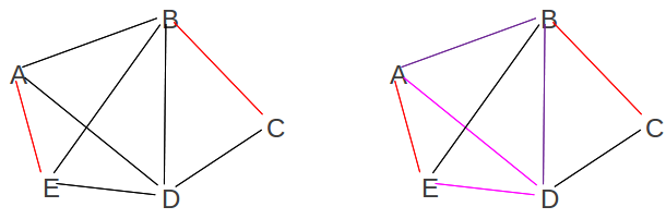
We now want to place a second call from A to E; we choose to route it
A--D--E. Next we want to route a call from A to D; the direct route is taken
by the previous alternate route and so we route it A--B--D. At this point,
only the B--E and C--D links are free. In retrospect, we would have been
better off routing the A--E call via A--B--E, so the A--D call could be
direct.
But the real issue is that, once alternate routes are allowed, most paths
now take up two links rather than one. Thus, on average we
now have more congestion -- almost double -- than before.
One common strategy when deciding whether to use alternate routes is to
avoid busy alternate routes; that is, if a trunk is
"close" to congested, then its channels may be reserved only by direct
routes and not by alternate routes. This would have blocked the second A--E
call above, and then allowed the A--D call to use direct routing. The usual
implementation is to reserve a small percentage -- say 10% -- of the
channels of a trunk for direct routes. The switch S1, above, would first
have asked for a direct channel to S3, but then, when trying alternates S4
and S5, would have asked for an "alternate" channel. Such "alternate"
requests would be denied by the trunk-channel allocator if the number of
idle channels was below the minimum.
Another strategy is called sticky routing: once an
alternate route is used, it is used preferentially for a while. That is, in
the picture above, if the A--E channels are all in use and we have another
A--E call to complete, we would first try A--B--E. If that was refused, we
would try A--D--E. If that now succeeds, then
in the future if we have another A--E call and the direct path is
busy we will try A--D--E first. The idea is that in finding the A--D--E path
the first time, we've found a relatively idle path (A--B--E was, after all,
showing signs of congestion), and we should keep using it until proven
otherwise.
Braess' Paradox
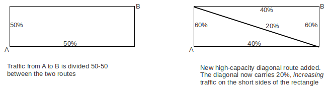
Adding trunk capacity doesn't necessarily help, due to Braess' Paradox:
sometimes additional trunks (or roads!) cause increased
congestion. This happens particularly when routing is done in a distributed
manner, with individual switches (or drivers!) all seeking to optimize
performance. In the following picture, the addition of a high-capacity
diagonal route actually makes things worse for the vertical short sides of
the original rectangle.
More central management of routing decisions can help (this is not
applicable to highway traffic!). Careful capacity planning can also help.
Switches
T-1, T-3, and SONET circuit-switching
A T-3 can be demultiplexed into its constituent DS-2's
(rare), DS-1's, or DS-0's.
A SONET STS-12 can be demuxed into all sorts of things,
eg
one STS-4
eight STS-1's
five of them are really DS-3's
one of them is a plain
IP-over-SONET
two are a "double-sized"
IP-over-SONET, at 2×STS-1 rate
Any given SONET line (portion with
no change in multiplexing) is a pure circuit-switched link.
Switching is done where the lines join together to form a path.
In general, in the phone system they like to avoid "full demultiplexing"
where possible, when dealing with DS-n lines. That's because demultiplexing
involves some overhead for these. For SONET, the overhead is negligible; we
can replace a single DS-0 in an STS-48 with relative ease.
Crossbars
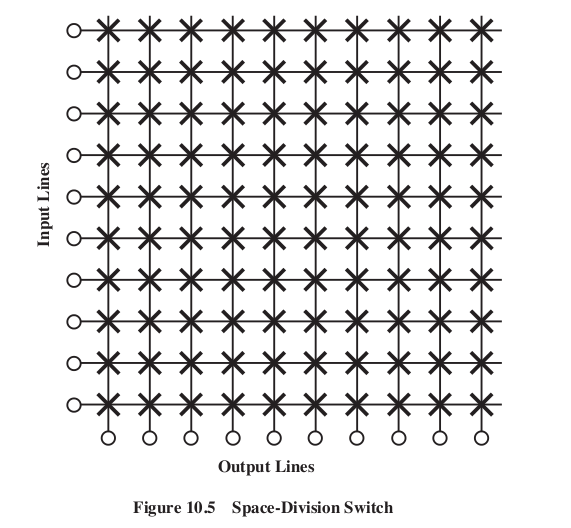
For connecting channels, the crossbar switch can be used (Stallings Fig
10.5). Any input line can be connected to any output line simply by closing
the switching unit at the intersection of the lines (the X's in the figure
below).
Crossbars were once made with electromechanical relays at each crossing
point; they can also be made with electronic switches. Crossbars allow any
input line to be connected to any output line. Furthermore, if the crossbar
is N×N, and we have any (permutation) map f:{1,2,3,..,N} ⟶ {1,2,3,...,N}, we
can connect input i to output f(i); that is, there are never any "conflicts"
or internal blocking.
However, crossbars are expensive.
So in the real world multi-stage
switches (Stallings Fig 10.6) are much more common:
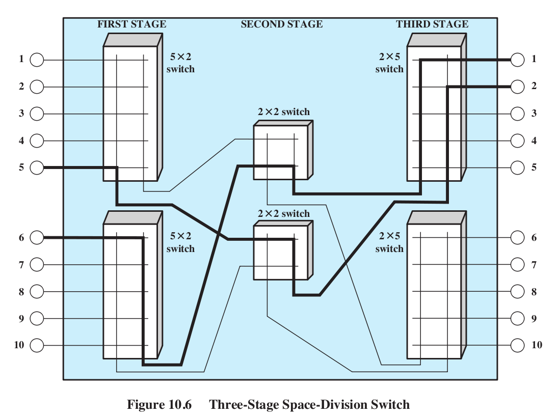
Note, however, that this switch blocks.
We cannot connect 2 in upper input half to 3 in upper output half, given the
existing connections. In general, we cannot have more than two connections
at a time.
Networks usually tolerate some degree of blocking.
A crossbar switch is an example of "space-division multiplexing"
These things are called "switch fabrics"
The inputs to these switches are the mux/demux channels.
Clos switches
This is the category of switch in Stallings' Fig 10.6. The concept itself
was first described in a 1953 Bell Labs paper by Charles Clos. The general
idea is the three-column "sparse crossbar" (in Fig 10.6, r=2, m=2, n=5)
Column 1: r many n×m crossbars. Total inputs: N = rn; total outputs: rm
Column 2: m many r×r crossbars. Total inputs: rm; total outputs: rm
Column 3: same as Column 1, wired in reverse (that is, r many m×n crossbars;
total inputs: rm, total outputs: rn).
The m outputs of each Column 1 n×m crossbar are connected to every one of
the r×r Column 2 crossbars.
Any connection is uniquely determined by its entry port (which port on which
Column 1 crossbar), its Column 2 crossbar, and its egress port. Note that
the specific port on the Column 2 crossbar is uniquely determined by the
wiring; we do not have to specify it.
All this replaces one large N×N crossbar, where N=nr. Because N=nr, n and r
are not independent; shrinking n raises r. Usually the minimum switch cost
is achieved when n is close to r, but not exactly.
The parameter m, however, is much more closely tied to cost. A larger m
makes the switch nonblocking (below). As m gets smaller, the switch "thins
down" and blocked calls become more likely. The picture above has m=2.
Suppose we take n≃m≃r; n≃r is a good balance, and m=n is the minimum n that
still guarantees reroute-nonblocking, below. Then n ≃ N1/2. The
size of the Clos configuration is = 2nmr + nr2 ≃ 3n3 ≃
3N3/2. The savings in space over the full crossbar is N1/2/3.
For N=1000 this is a factor of 10; for N=10,000 it is a factor of 30.
Fact 1: if m ≥ 2n−1, then the switch
is completely nonblocking: any free
input on the left can be connected to any free output on the right.
Proof: Here's the simpler case where m = 2n−1; the m > 2n-1 case is the
same, but you use inequalities.
Consider the left and right-hand n×m and m×n crossbars that we wish to
connect: these are the entry and egress crossbars. Each has at most n−1
active inputs, and thus at most n−1 active outputs, and thus at least
m−(n−1) free outputs. The
hypothesis means m−(n−1) = m−n+1 = 2n−1−n+1 = n, so there are at least n
free outputs.
The entry crossbar thus has at least n free connections to column 2, and
there are similarly n free connections from column 2 to the egress crossbar.
We need to show that there is at least one column 2 crossbar has a free
connection to both the entry and
egress crossbars. But this has to happen, because there are m = 2n−1 column
2 crossbars, and n connected to the entry crossbar and n connected to the
egress. If there were no overlap in the set of column-2 crossbars connected
to the entry and the set of column-2 crossbars connected to the egress, then
there would have to be at east 2n column-2 crossbars in all, which there are
not.
Fact 2: if m≥n, then the switch is reroute-nonblocking:
any input can be connected to any output provided
that we are allowed to reroute some
existing connections to a different Column-2 crossbar to make room. Note
that all we have to specify for an existing connection is which Column-2
crossbar it is to use.
Blocking/rerouting example 1: Nine
3×3 crossbars arranged in a 3x3 pattern. There are three existing
connections, designated by which crossbar in column 1 connects to which
crossbar in column 3 (actual ports don't matter). Let us refer to the middle
column crossbars as M1, M2, and M3.
- row 1 to row 2, via M1
- row 2 to row 1, via M2
- row 3 to row 1, via M3
We now wish to add one new connection from row 1 to row 1; this should be
doable, as the row 1 column 1 switch has one of its three inputs in use, and
the row 1 column three switch has two of its three outputs in use.
However, we cannot use any of the column 2 switches to complete the circuit:
for M1, the line to the entry switch is blocked, and for M2 and M3, the line
to the egress switch is blocked.
The call becomes possible if we move connection 1 so that it uses M2,
freeing M1 for the new connection. Or we can move connection 2 so that it
uses M1, freeing M2 for the new connection.
Blocking/rerouting example 2:
Consider the example below, from http://en.wikipedia.org/wiki/Nonblocking_minimal_spanning_switch.
We have m=n=r=4 (m=n is part of the example; making r=3 would eliminate the
bottom switch in the first and third columns, and make the middle column
switches (of which there would still be 4) be 3×3). Connections A-A (red),
B-B (green), C-C (orange) and D-D (blue) have been made, and we want to add
a connection from E to E. However, we're stuck. If the middle column of
switches are numbered 1,2,3,4 from top to bottom, then E can only connect to
3 and 4. However, 3's output to the E switch in the third column is in use
(orange), and 4's output (blue) is also in use.
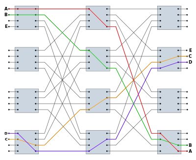
However, we can move a call: there
are several possibilities. One is to move the B-B (green) path from middle
switch 2 down to 3, freeing up the E-E connection to use middle switch 2.
Another is to move the blue D-D connection up. If we move it to middle
switch 2 then the E-E connection is still blocked, but we can move it to
middle switch 1 and then we can connect E and E through middle switch 2.
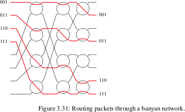
Banyan switches
Banyan switches can replace a full N×N crossbar with (N/2)*log(N) switches,
arranged in (N/2) rows and log(N) columns. Each switch has two inputs, so a
column of N/2 switches has N inputs. For banyan switching, however, each
input must be prefixed with a
binary routing string (of length
log(N) bits) representing the output port. In a sense, this means that each
data unit is a "packet", though a packet with what might be called a microheader.
The body might consist of one to a few bytes.
Each switch element has two inputs and two outputs. The element uses the
first bit of the prefixed routing string to decide which output to use, and
then discards that first bit (so the next switch makes its decision based on
the second bit, etc).
Banyan networks may involve collisions, in principle: two inputs
may be active at the same time. In practice, a mesh can be constructed so
that collisions never occur, so long as the inputs that enter the switch
fabric simultaneously are sorted
by their routing strings: eg 001, 101, 110, 111.
It is common to run unsorted inputs through a sorting fabric
first, so as to avoid having to take any concrete steps to achieve this. One
convenient sorting fabric is the Batcher network; it sorts N inputs with N
log2(N) nodes. Micropackets enter the network at the left; the
vertical segments perform a compare-and-swap operation.

Slightly more efficient Batcher networks can be created if we know we are
sorting on compact bitstrings.
Brief look at Signaling System 7
SS7 is the call-setup-and-management system for large
telephone providers, for both intra-provider and inter-provider
communication. Here we outline some features for the call-setup /
call-teardown parts. SS7 can do other things as well.
SS7 introduced common-channel signaling (also called out-of-band
signaling), which means a set of separate communications channels
reserved for signaling (all signaling shares a common channel; signals and
voice do not). The older strategy sent the signaling data down the
voice channels, before the voice path was set up. (In the US, this would
have been the CCITT R1 protocol, the one vulnerable to the 2600 Hz attack.)
Mostly SS7 is used only to communicate between central offices, not to
"customer premises".
The portion of SS7 that includes call setup and teardown is ISUP: ISDN User
Part. We've already seen one ISUP attribute: the Provider-Asserted Identity
(or P-Asserted Identity or PAI) attribute in a SIP header, identifying the
caller.
A small amount of SS7 signaling is not associated with a particular call.
Examples include:
- Updating telephone databases
- Tracking cellphones and updating their location (this may occur either
without a call in progress or at mid-call)
- Delivering SMS messages
- Declaring some voice channels to be out of service, or back in service
SS7 signaling can be associated or quasi-associated.
Associated signaling means that the signaling traverses roughly the same
path as the call. That is, the signaling might traverse the same sequence of
switches that the call will later traverse. Quasi-associated signaling means
that signaling passes through signal transfer points
(STPs) that may not be on the eventual voice path. In fact an entirely
separate control network (or "control plane") might be set
up for the signaling communication. When quasi-associated signaling is used,
each switch along the call route must still be notified of what two channels
should be tied together.
Quasi-associated signaling is the dominant mode in North America, except
within relatively small SS7 domains (eg within Local Exchange
Carriers, or LECs).
SS7 defines three types of nodes, or service points (SPs):
- STP nodes: Signal Transfer Points, like general
router nodes. These form the "STP backbone" of the SS7 network.
- SSP nodes: Service Switching Points, which are phone
switches. These are the communication endpoints for SS7
- SCP nodes: Service Control Points, such as databases
and other central server nodes.
SCP nodes host a variety of databases:
- 800-number lookup
- Local-Number-Portability (LNP) lookup
- E911 (Extended 911) address lookup for VoIP lines
Internetworking layer
Routes are configured ahead of time, and consist of bundles (or linksets)
of DS0 channels ("links") set aside for this purpose. So-called High-Speed
Links are also used, eg DS1 links. Recall that a DS1 channel is essentially
just a bundle of 24 DS0 channels. There are several types of links: A, B, C,
D, E, and F:
- A: Access links
- B: Bridge links
- C: Cross links
- D: Diagonal links
- E: Extended links
- F: Fully associated links
Access links connect "leaf-node" SSP/SCP nodes to the STP backbone. In North
America, most SSPs connect to STPs, not to other SSPs.
Normally, A-links (and most other links) are allocated in pairs for an
anticipated data volume that would not fill one link, so that if one of the
two links fails then the other can take 100% of the combined load.
STPs are usually also paired for redundancy; each SSP/SCP leaf node is
joined to a mated STP pair by a pair of A-links.
The two STPs forming a mated pair are joined by C links. B
links connect mated STP pairs to other mated pairs, forming much
of the STP backbone. D links do the same, but are links
between STPs of different SS7 networks (eg between an IXC and a LEC). Even
in the telecom world this distinction is not always recognized as important
and so these are known as B/D links.
E links connect leaf-node SSP/SCP nodes to the STP
backbone, but are provided as alternative paths; they are connections from
an SSP/SCP to a "non-home" mated STP pair.
Finally, F links join SSPs (switches) directly. Associated
signaling traffic, traveling from switch to switch, will usually take F
links between adjacent switches. In such traffic, the destination address
(or point code) will match the address of the receiving SSP; in
quasi-associated signaling, the destination address will not match the
receiving STP and the receiving STP will be responsible for forwarding the
message to the next STP in the route.
From http://www.ss7-training.net/sigtran-training/ch04lev1sec3.html:

When a link is idle (that is, it is not carrying messages), it carries link-status
packets. This provides for continuous monitoring of link
performance. A design goal is to "never take no for an answer".
Between two given SPs (quite possibly nonadjacent) a number of predetermined
routes may be defined; the collection of these is known as a routeset.
Destination addresses are 32-bit numbers, called point codes.
Routing is not static, to be able to handle failed links.
Signaling is sent as packets, with a special (non-IP, non-OSI) format. The
physical, LAN and Internetwork layers are known as MTP1, MTP2 and MTP3,
respectively, or collectively as MTP. Header addresses are provided at the
MTP3 level.
Here is a sample low-level packet format:
FLG - Opening
Flag
8 Bits
BSN - Backward Sequence
Number 7 Bits
BIB - Backward Indicator
Bit 1 Bit
FSN - Forward Sequence
Number 7 Bits
FIB - Forward Indicator
Bit 1 Bit
LI - Length
Indicator
6 Bits
MSG - Message
Bits
variable
CK - Check Bits
(CRC) 16 Bits
FLG - Closing
Flag
8 Bits
Note the lack of an address field! This is because this protocol runs over
DS0 point-to-point links. Addresses (point codes) are used at higher levels,
eg within the ISUP part (ISDN User Part):
Origination Point Code
Destination Point Code
Signaling link
Circuit ID
Message type
Fixed part
Mandatory Variable Part
Optional part
Point codes (addresses) are typically unique only within national
boundaries! This causes difficulties routing international calls [http://www.cnp-wireless.com/ArticleArchive/Wireless%20Telecom/2002Q4-SS7vsIP.htm].
SS7 is used between phone switches, both within a company
(to do the above setup) and also between companies. In the latter setting,
some of its capabilities include
- I am forwarding to you a call placed from 212-555-1234 to
312-555-5678. It will be on trunk 067
- may be sent to the final LEC
- may be sent by the originating LEC to a long-distance provider
- Someone just dialed 800-555-1212. How do I route this?
- Someone just dialed 911 from a cellphone; where are they?
- Someone just dialed 911 from a VoIP phone; where are they? (Note this
is completely different from the cellphone example)
- The party called for the call on trunk 1027 has answered. Please start
billing.
- The party called for the call on trunk 1035 is busy. Please let the
caller know, and release the trunk.
- The route to Adamant is congested. Avoid sending calls there, unless
they are high-priority.
- Trunk 068 has been removed for service
LECs use SS7 to get their T-carrier/SONET lines to work with others.