Entity-Relationship modeling
Entity-Relationship modeling
This is a variant (actually a predecessor) of object modeling (eg UML or CRC
cards or Booch diagrams). In the latter, everything is an object. In ER
modeling, we will make a distinction between entities
(things) and relationships. As a
simple example, students and courses are entities; but the enrolled_in
table is a relationship. Sections most likely would be modeled as entities
too, though there is a relationship to COURSE.
The ER process starts, like most software-engineering projects, with
obtaining requirements from users. What data needs to be kept, what queries
need to be asked, and what business rules do we build in? (For example, if
the DEPARTMENT table has a single column for manager, then we have just
committed to having a single manager for each department.)
The goal of the E-R modeling process is to create an E-R
diagram, which we can then more-or-less mechanically convert to a
set of tables. Both entities and relationships will correspond to tables;
entity tables will often have a single-attribute primary key while the key
for relationship tables will almost always involve multiple attributes.
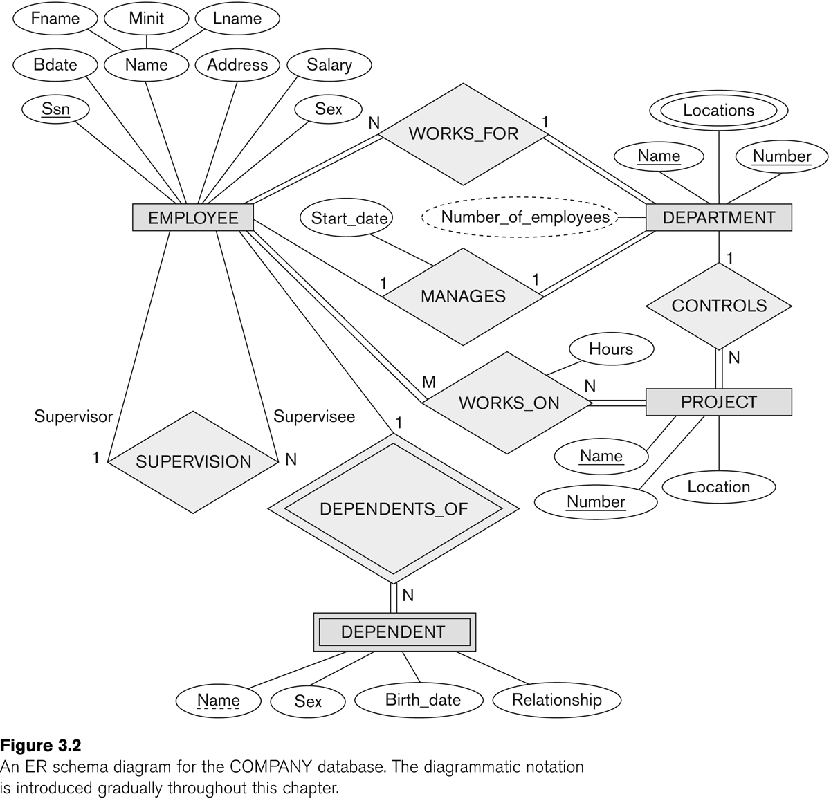
Here is an E-R diagram for the OFFICE database. (The figure below was
Fig 3.2 in an earlier edition of E&N; it is Fig 7.2 in the 6th edition.)
This style of diagram was introduced by Peter Chen in 1976, and is
sometimes known at the Chen format. It is well-suited to
conceptual and logical modeling of a database, in that it
makes a clear distinction between entities and relationships.
Entities
The first modeling step is to identify the entities.
These should represent physical things, such as employees or parts or (more
abstractly) departments. Note that customer_orders might be modeled as an
entity at this point, but might also be modeled as a relationship.
Entities have attributes, which
will later more or less become the fields. For each attribute we have the
following aspects:
- composite v single: a social-security number is a single attribute; an
address (consisting of street, apt, city, state, zip) would be
composite. So would a name.
- single-valued v multi-valued: E&N's examples here are
college_degrees and vehicle_color.
- stored v derived: the classic derived attribute is age, derived from
birthdate.
We also must decide which attributes can be NULL.
Attributes at this point should not be references to other tables; instead,
we will create those references when we create relationships.
The book uses () to represent sub-attributes of composite attributes, and {}
to surround multi-valued attributes.
Traditionally we represent the entity with a rectangular box, and the
attributes are little oval tags.
An entity type is our resulting
schema for the entity; the entity set
is the actual set of entities.
In the diagram, we will underline
the key attributes. If a key is composite, say (state,regnum), then we make
a composite attribute out of those pieces.
This is a slight problem if the key can be either (state,regnum) or
(state,license_plate); how could we best address this?
Note that key attributes really represent constraints.
In the early stages, we allowed entity attributes to be composite or
computed or multi-valued; all of these will eventually be handled in
specific ways as we translate into SQL.
Often there is more than one way to do things. In the COMPANY example, we
might list dept as an attribute of
EMPLOYEE, and eventually conclude that because dept
represented an instance of another entity (DEPARTMENT), we would have a
foreign-key constraint on EMPLOYEE.dept, referring to DEPARTMENT.dnumber.
Note, however, that we could
instead list employees as a
multi-valued attribute of DEPARTMENT. One reason for not doing this is that
we do want to minimize the use of multi-valued attributes, but this
arrangement would have been a possible option. Later, we even could implement
this second approach by adding an attribute dept
to the EMPLOYEE table (the table, not entity).
We actually could have both forms,
but we would need to understand the constraint that if employee e is in the
employees multi-valued attribute for
DEPARTMENT d, then department d must be be the value of the EMPLOYEE e's dept attribute. That is, the dual
attributes would have to be inverses.
As for naming entities, a common practice (used by E&N) is to name them
with singular nouns. Nouns because they should represent things; singular
for the individual objects. Eventually we will have a table of employees, plural, but we call it EMPLOYEE to
represent what entities it contains.
Weak entities
The usual definition of a weak entity is that it is an entity that does not
have key attributes of its own. The classic example is the DEPENDENT entity,
with attributes name, birth_date,
sex and relationship;
a dependent is uniquely determined by the name
and the employee to whom the dependent is associated. You might wonder why
we don't add an attribute employee
at the beginning, and have ⟨name, employee⟩ be the key. One problem with
that approach is that employee is a
reference to a different entity; such references should really be described
as relationships. After all, the EMPLOYEE is really someone else, not an atomic
attribute of the DEPENDENT person itself (the other attributes of DEPENDENT
are atomic). We will say, instead, that there is a relationship
between the DEPENDENT entity and EMPLOYEE; this relationship is the identifying
relationship for DEPENDENT.
In general, during the design process, the statement that "dependents do not
have a key" is subject to interpretation; we can
always declare that the associated employee's SSN is part of the key.
However, the point is that dependents do not have a "natural" key that is an
attribute of the dependent itself. Also, using the "employee_ssn" as an
attribute is suspect because it realistically is an attempt to refer to
another table.
There is a total participation constraint
between DEPENDENT and EMPLOYEE; every DEPENDENT must be connected to some
EMPLOYEE. As the book points out, however, every DRIVERS_LICENSE is
associated with some PERSON, but the DRIVERS_LICENSE entity does in fact
have its own key: the drivers_license_number.
The way that DEPENDENT could become a strong entity is if we added its own key: dependent_ssn. But typically
the SSNs of dependents are not known (minor dependents may not even have
SSNs), so we choose not to implement the database this way.
The DEPENDENT entity does have a partial
key: the attribute name,
which, together with the associated EMPLOYEE object, does define a key.
We could also represent dependents
as a multi-valued, composite attribute of EMPLOYEE.
Fig 7.8 (6th-edition numbering) lists all the entities:

Entity summary
Here's a summary for the construction of entities:
- Look for the "concrete" objects in the problem domain
- List the attributes of each entity.
- Break compound attributes down into atomic attributes
- Attributes can, at this stage, be multivalued
- Indicate the (single-attribute) key for each entity
- Do not use other entities as
attributes; model this instead at the relation stage
- This may leave some entities ("weak" entities) without a complete key.
Just mark them as such
- Weak entities will be tied to some other entity through the defining
relationship.
Relationships
Initially we arrive at Fig 7.8, with four
entities: DEPARTMENT, PROJECT, EMPLOYEE, DEPENDENT. Note that Works_on here
is shown as an EMPLOYEE attribute; it could also be represented as a PROJECT
attribute. How are we representing department membership? Who works on what?
Who is in charge of what projects?
Note some of the attributes in figure 7.8
refer to other entities. These are our first relationships; these will
likely end up translated into foreign key
constraints.
A relationship formally is a set of
ordered tuples ⟨e1,e2,...,en⟩ where each ei
is a member of entity Ei. Some entities here may simply be
attributes (eg the hours attribute
of the WORKS_ON relationship ⟨employee,project,hours⟩.
The tuples in a relationship must each have a clear meaning to the
application. Relationship names are usually verbs, and should make sense
"left to right" (and sometimes top to bottom). That is, we would prefer the
relationship name supervises
because it fits in with
SUPERVISOR----- supervises
------EMPLOYEE
We could also use
EMPLOYEE ----- reports_to
------ SUPERVISOR
Most relationships are binary (possibly with added
attributes); ternary and higher-degree relationships are less common (and
less tractable).
In early stages we may model a relationship as a (typically multivalued)
entity attribute; consider again how we modeled WORKS_ON in Figure
7.8.
When a relationship involves multiple entities, we can assign a role
name to each entity. Commonly this is just the name of the entity
(eg EMPLOYEE), but in relationships between an entity and itself (so-called
recursive relationships), we have to
use different names. Consider the example of the SUPERVISES relationship.
Example: fig 7.11; note that the righthand
SUPERVISION oval contains references to pairs
of entities in the lefthand EMPLOYEE oval. (Which numeric label is used to
indicate the supervisor?)
For entities, it is often the case that we elect to use synthetic
keys: arbitrarily generated "ID numbers". This makes sense for
departments and employees. Relationships, however, typically have a natural
key consisting of one primary key from each entity; using synthetic keys (eg
order numbers) should stand out. A good example of this is the GRADE_REPORT
table, indexed by student_number and section_identifier (and with attribute
grade).
How should we model SECTION in the school database? We did model it as an
entity, but could we model it as a ternary relationship between course,
semester, and instructor? No, if we allow an instructor to teach two
sections of the same course in the same semester.
What about an INVOICE? This consists of a number of ITEMs, each with
quantity, ordered by a single CUSTOMER. We can create a relationship ORDERS
between CUSTOMER and ITEM, but an invoice is more than that. If a customer
places multiple orders on the same day, the customer likely expects them to
remain different. So instead we might choose to have an entity
for INVOICE, with attributes invoice_number (synthetic), and date, and
customer, and then create a relationship ORDERS between INVOICE and ITEM,
with attributes for price and quantity:
invoice
|
item
|
price
|
quantity
|
1002
|
37
|
$5
|
6
|
1002
|
59
|
$3.45
|
2
|
1003
|
101
|
$1300
|
1
|
See invoice.
Cardinality
Binary relationships can be
classified as 1:1, 1:N, N:1, or M:N. In the WORKS_FOR relationship, between
DEPARTMENT and EMPLOYEE, this is 1:N. Each employee works for 1 department,
but a department can have multiple employees. (Again, the 1 here in 1:N
represents a constraint; the N represents no constraint. It is not actually
required that all departments have multiple employees.)
The MANAGER relationship is 1:1 (though see the note): every dept has one
manager and vice-versa. This is a 1-1 relationship between EMPLOYEE and
DEPARTMENT. Note that most employees are not managers; this does not change
the fact that no employee manages two departments. See Fig
7.12 for a diagram representing this.
Note: that the MANAGER relationship is 1:1
expresses a business rule: no
employee manages more than one department, and no department has two
managers. The latter is pretty universal; the former, while common, is
not.
Many relationships are 1:N (one-to-many):
DEPARTMENT ----1--- employs ----N-----
EMPLOYEE (or employee works_for department)
EMPLOYEE -----1----- supervises ----N------EMPLOYEE (boss
is on left side)
DEPARTMENT ----1---- controls-----N------PROJECT
Think of "1 department = N employees"; the 1 goes on the side that the other entity can have only 1 of. The 1
goes on the "larger" unit: a department is made of N employees, a boss
supervises N employees, a department controls N projects.
See Fig 7.9.
The supervises relationship is "recursive" (a better word, used in the UML
community, is "reflexive"). See figure 7.11
for a diagram.
The WORKS_ON relationship is M:N.
Similarly, the enroll relationship is M:N
STUDENT -----M----- enrolls ----N----SECTION
A section may have several students; each student may enroll in several
sections.
See fig 7.13 for a diagram of the WORKS_ON
relationship.
What do we do if, after we've gotten started, we decide that the location
attribute of a DEPARTMENT should be multi-valued? We can model multi-valued
attributes as relationships instead:
DEPARTMENT ----N----is_located_at-----M----LOCATION
Clearly, we would not want this to be 1:M, which would mean that a location
could be used by only one department. If we do decide that departments have
single locations, we go back to an N:1 relationship:
DEPARTMENT ----N----is_located_at-----1----LOCATION
Participation constraints on relationships
Suppose every employee must work for some department. Then the WORKS_FOR
relationship involves total participation
of the EMPLOYEE entity. The MANAGES relationship involves partial
participation of the EMPLOYEE entity, at least as far as supervisors are
concerned.
We represent total participation by a double line, and partial by a single
line.
Relationships can have attributes; eg hours
of WORKS_ON or grade for the
GRADE_REPORT table.
As was described above, entities usually have a single (possibly composite)
key; entities are often given a synthetic
key (ie an employee_id or student_number). Relationships typically have a
key with as many attributes as the degree of the relationship. Synthetic
keys are often awkward for these.
The key to a relationship should be a composite of the keys to each entity.
Otherwise the relationship is not just about the two entities involved.
Note that synthetic keys work very well for joins.
Now we should be able to go through Figure 7.2 (E&N p 204, below) in
detail. The relationships are supervises, works_for, manages, controls,
works_on, and dependents_of. Note that the name "supervision" is awkward; it
is not clear who is supervising whom. As a result, the entity links need
annotation with the role names "supervisor" and "supervisee". However, such
annotation is often a good idea for clarity.
(The figure below was Fig 3.2 in an earlier edition of E&N; it is Fig
7.2 in the 6th edition.)
Sometimes, as we rethink things, an attribute can be changed to a
relationship, or vice-versa. Sometimes an attribute may be promoted to an
entity, particularly if it was used in several other entities, in which case
we may also add a relationship to
those other entities.
Relationship attributes can sometimes be moved to entities. For a 1:1
relationship, the relationship attribute can be moved to either entity. For
a 1:N relationship, the relationship attribute can only be moved to the N
side. Consider the earlier examples:
DEPARTMENT ----1--- employs ----N-----
EMPLOYEE attribute: start_date, etc
EMPLOYEE -----1----- supervises ----N------EMPLOYEE
attribute: review_date
DEPARTMENT ----1----
controls-----N------PROJECT attribute:
project_budget_num
Sometimes we have entity attributes that need to be translated into
relationships. See Section 7.6. We would move manager information from the
DEPARTMENT entity to the MANAGES relationship. We started out with manager
as an attribute of departments, but later realized that there was a
relationship involved because two
entities were involved: DEPARTMENT and EMPLOYEE. This suggests the need for
a relationship.
We would move controlling-department information from the PROJECT entity to
the CONTROLS relationship. We would remove department, supervisor, and
works_on from EMPLOYEE. Note that some of these will eventually be added
back. At this point, we should have eliminated most multi-valued attributes.
Entities usually have a single (possibly composite) key; entities are often
given a synthetic key (ie an
employee_id or student_number). Relationships typically have a key with as
many attributes as the degree of the relationship. Synthetic keys are often
awkward for these.
The key to a relationship should be a composite of the keys to each entity.
Otherwise the relationship is not just about the two entities involved.
Note that synthetic keys work very well for joins.
ER diagram for the STUDENT database
Entities:
- student (name, student_number,
class, major)
- course (course_name, course_number, credit_hours, department)
- section (section_identifier, semester, year,
instructor) // why not
course_number?
Relationships:
course----< PREREQUISITE >---- course
section----< IS_OFFERING_OF >---- course
student ----< REGISTERS_FOR >---- section
(min,max) annotation
Instead of labeling lines connecting a relationship to an entity with 1, M,
or N, we can also use a (min,max) notation, meaning that each entity e in
the entity set E must participate in at least min entries of the
relationship, and at most max. If min>0, the participation is total;
min=0 means partial participation. The max is denoted N when we mean it is
allowed to be >1.
Note that a 1-N relationship would have the values reversed using the
(min,max) notation:
DEPARTMENT ===1=== employs ===N===
EMPLOYEE // 1 dept
= N employees
DEPARTMENT -----(1,N)---- employs --- (1,1)-----
EMPLOYEE // dept can have 1..N employees
The second line, above, means that a given department can appear multiple
times in the EMPLOYS relationship; ie a department can have multiple
employees. An employee can appear only once; that is, can work for only a
single department. Every employee must appear at least once, and every
department.
(Recall that the parallel lines === in the first line above represent total
participation: every department has an employee, and every employee works
for some department. This is represented in the second line with the 1 as
the first coordinate of each pair.)
Full example of (min,max) annotation: Fig 7.15
Why do they say
department ----(4,N)---employs
----(1,1)----employee
?
Manages relationship: put into entity on (1,1) side rather than entity on
(0,1) side
(0,1) doesn't say anything about how often the participation can be 0.
Consider
department --- MANAGED_BY------- (0,1)-----manager
(employee)
supervisor --- SUPERVISES --- (0,1)---
supervisee (employee)
Most employees are not managers.
Almost all employees are supervised.
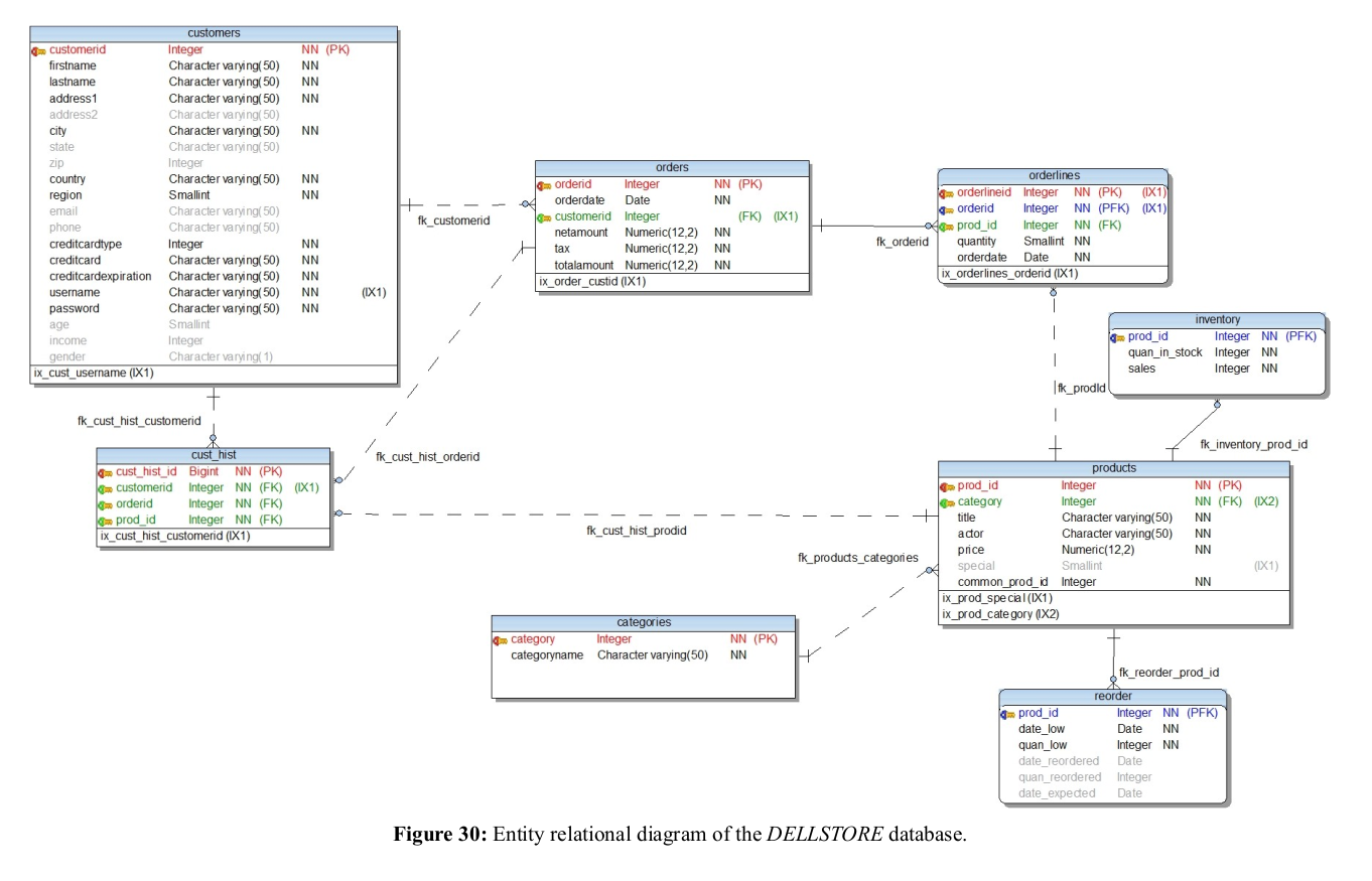
Crows-foot diagrams
The above Chen-style diagrams are characterized by separate symbols for
entities and relationships; they are best suited for so-called logical
design, before the relationships are translated into tables. For
describing the physical model of a database, the
so-called crows-foot notation is often useful. In this
notation, there is a box for each table. The box lists the attributes of
that table, identifying keys. Boxes represent entities after the
relationships have been transformed into entity attributes or into new
tables, as appropriate.
Lines between boxes represent relationships, and are often associated
with foreign-key constraints. Dashed lines are used for ordinary
relationships, and solid lines for weak-entity relationships.
Relationships don't get their own boxes because at this point they have
been reduced to entities (that is, tables), and thus no longer have their
own attributes.
Cardinality is represented by how the ends of these lines are decorated.
Here are the basics:
────┼ one
────< many
───┼< one or many
──o─< zero or many
───┼┼ exactly one
For an example, see dellstore.png.
Note that, in this example, some of the "crows' feet" get partially
obscured by the drop-shading on the boxes.
UML diagrams
See Figure 7.16. The previous example, dellstore.png, is similar. UML diagrams
have space for operations,which in
the world of databases we're not much concerned about. The big boxes are for
entities; relationships have been reduced to boxes that annotate links. A
(min,max) notation is used, but the label goes on the opposite
entity.
UML relationships (actually, ER relationships as well) may either be of association or of aggregation.
As examples of the latter we have:
- Employees have dependents
- Projects have a location
- Departments have a location
How do we translate this to tables?
We'll get to this next, but note that a 1:1 relationship can be represented
as an attribute of either entity. A
1:N relationship can be modeled as an attribute of one
of the entities (the entity on the side of the N). M:N relationships must
get their own table.
ER-to-relational mapping
How do we build a database schema from an ER diagram?
Step 1: regular entities
We define a table for each non-weak entity. We use all the leaf attributes;
composite attributes are represented by their ungrouped components. Keys are
also declared. Attributes that were earlier pushed into relationships are
not yet included.
Step 2: weak entities
We create a table for each weak entity, adding the keys for the owner entity
type (or types) (this would mean employee ssn), and adding a foreign
key constraint to the owner-entity table.
We are likely to use the CASCADE option for drop/updates: if an employee ssn
is updated, then the dependent essn must be updated, and if an employee is
deleted, then all the dependents are deleted too.
Step 3: binary 1:1 relationships
Let S and T be the participating entities to 1:1 relationship R. We pick one
of the two -- say S -- and add to S a column that represents the primary key
of T, and all the attributes of R.
It is better to choose as S the entity that has total (or at least closer to
total) participation in R. For example, the manages relationship between
departments and employees is 1:1, but is total only for DEPARTMENT, and is
nowhere near total for EMPLOYEE. Thus, we add a column manager
to DEPARTMENT. However, adding a column manages
to EMPLOYEE would work.
We also add a foreign key constraint to S, on the new attribute, referring
to the primary key of T.
One alternative is to merge S and T into a single relationship; this makes
sense only if both have total
participation in R. This means that S and T each have the same number of
records, and each record s in S corresponds to exactly one t in T.
A third alternative is to set up a table R containing ⟨sk,tk⟩ key pairs.
Step 4: binary 1:N relationships
Let us suppose S---N---R---1---T. We now add T's key to S as an attribute
with foreign-key constraint. We must
add T's key to S; we cannot do it the other way around. In the relationship
DEPARTMENT ----1--- employs ----N----- EMPLOYEE
we would have S be EMPLOYEE; we would put a dno
column in EMPLOYEE (why can't we add an essn column to DEPARTMENT?)
An alternative is the ⟨Skey,Tkey⟩ keypair table. This might be more
efficient if only a few s in S participate in the relationship; otherwise we
would have many NULLs in the T-column of S.
Step 5: binary M:N relationships
Here we must create a table R of tuples including the key of S (sk), the key
of T (tk), and any attributes of R; we can not
push the data into either S or T. Call the new table also R (note that
E&N call it S). The sk column of R should have a foreign key constraint
referring to the key column of S, and the tk column of R should similarly
have a foreign key constraint to the key column of T.
The WORKS_ON table is a canonical example; so is the GRADE_REPORT table.
Again we would likely to use the CASCADE option for deletion or update of
records in the participating entities S and T.
Step 6: multivalued attributes
If we have any left, they must be moved into their own tables. For example,
if employees can have several qualifications
(eg degrees or certifications), we would create a table QUALIFICATION with
two columns: essn and qualification. The DEPT_LOCATIONS table is similar.
Again, we would have an appropriate foreign key constraint back to the
original table.
Step 7: higher-degree relationships
These are handled like binary M:N relationships. Sort of.
More on Foreign Keys
Here's the seven-step ER-to-relation algorithm again, slightly simplified:
- create a table for each regular entity
- create a table for each weak entity, adding the key field from the
owner entity as a foreign key for the new entity. Example:
table Dependents, with a column essn referencing Employee.
- for binary 1:1 relationships between entities E1 and
E2, pick one of them (eg E1) and add to it a field containing the key to
E2. Make this a foreign key in E1. Example: the
dept-manager relationship, implemented as column mgr_ssn in table
Department.
- for binary 1:N relationships between E1 and E2,
E1---1---R---N---E2, add a column to E2 containing the key of E1 (we can
not implement the relationship with a column in E1!).
Make this new column a foreign key in E2, referencing E1. Example:
the works-for relationship, implemented as column dno
in table Employee.
- For binary N:M relationships between E1 and E2,
create a new table R consisting of ⟨E1.key, E2.key, R.attributes⟩. Make
E1.key and E2.key foreign keys in R. Example: The
works-on relationship, implemented as a table which has
as key the pair ⟨essn,pno⟩, each of which are keys to their respective
tables.
- For multivalued attributes of entity E, create a new relation R. One
column of R will be E.key; this should be a foreign key in R.
- ternary and higher-degree relationships: like step 5.
Joins arise in steps 2, 3, 4, 5, 6,
and 7, for recovering the original
relationships (or attribute sets for 6, or entities for 2). In
every case, the join field is a key of one relation and a foreign
key in the other.
Not all joins are about recovering
relations from an ER diagram.
Also, I said earlier that entity T should not have an attribute that was
another entity of type S; instead, we should create a relationship R between
T and S. If S was at all a candidate for an attribute,
each T would be related to at most one S and so this would have cardinality
constraint T---N---R---1---S. Then, when we did the above conversion, in
step four we would add S's key to T with a foreign key constraint referring
to S.
But suppose we did add S as an
entity attribute to T. Then we would end up with the same situation: we
would use the key of S as an
attribute of T, and create the same foreign-key constraint. So in the end we
get the same thing.
Invoice
How shall we model invoices? An invoice is a collection of parts ordered,
each with a quantity. One way is to try to model an invoice (or at least an
invoice_item) as a binary relationship between CUSTOMER
and PART, with attributes date and quantity. An invoice is thus all the
items to the same customer with the same date.
CUSTOMER---<INVOICE_ITEM>---PART
/ \
date quantity
An invoice would be uniquely determined by the date and customer, so if
Customer c ordered Part p on Date d with Quantity q we would have ⟨c,p,d,q⟩
∈ Invoice. Given ⟨c,d⟩ we can look up all the parts p and, for each part,
the quantity.
For a given c and d there might be multiple parts p that were part of the
invoice. We can search the Invoice table for those ⟨c,d⟩, and find the
balance of each record.
Problem: INVOICE is not actually a
"relationship set" for entities Customer and Part, as defined in EN6 §7.4.1;
a relationship would have to be a subset of the cross product Customer ×
Part; we can add attributes, but the
⟨c,p⟩ part is supposed to determine the record. However, the values
of c and p do not determine an
INVOICE record. The key for INVOICE is the triple
⟨c,p,d⟩; a customer c can order 100 units of d on 2005-12-01 and then 200
more units on 2006-01-27.
If we want INVOICE to be a relationship, we need to recognize that it is
really a ternary relationship
between Customer, Part, and a single-attribute entity Order_Date. Ternary
relationships tend to be inefficient. None of the relationships in the
COMPANY database were ternary; in WORKS_ON, a record was uniquely determined
by the essn and the project_num; in WORKS_FOR, by the ssn and the dept_no.
Even if we do this, we have another issue: if a customer places multiple
orders on the same day, the customer likely expects them to remain
different.
So, instead, a much more common approach (which also allows multiple
invoices on a single day) is to make Invoice an entity,
with synthetic key invoice_num.
That is, we declare that orders are "things" rather than relationships. This
is an instance of a rather general strategy that might be called the synthetic-key trick: convert a putative
relationship to an entity by assigning a "serial number" to each tuple in
the relationship. In this case the synthetic key has a natural
interpretation: we number each order as it is placed. For the works_on
relationship of the COMPANY database we might use a synthetic key called
Job_Assignment_Num; for the Works_For relationship between Employees and
Departments we might use Job_Association_Num.
After we create an entity Invoice, with attributes Cust_id
and Order_date and identified by invoice_num, we will create a relationship
Invoice_Item, between Invoice and Item, with attributes for price and
quantity. This table effectively lists what a given Invoice actually
includes:
Table Invoice_Item
invoice
|
item
|
price
|
quantity
|
1002
|
37
|
$5
|
6
|
1002
|
59
|
$3.45
|
2
|
1003
|
101
|
$1300
|
1
|
Relationship Invoice_Item is often called Orders: the relationship
identifies all the items ordered.
Invoice ---------
Invoice_Item ---------- Part
|
quantity
(Actually, Invoice also has a relationship Ordered_By to Customer; that is
N:1 so I have immediately implemented it by adding a Cust_id attribute to
Invoice. We replaced one sort-of-binary relationship Invoice between
Customer and Part with a new entity
Invoice with binary relationships to each of Customer and Part. But only the
relationship with Part is M:N and so needs it own table.)
We implement Invoice_Item as its own table listing invoice numbers, part
numbers and quantities. The primary key is the pair ⟨invoice_num, part_num⟩;
the table also has an attribute for quantity (and perhaps also for
current_price, or for discount). The INVOICE table (table Orders in the
dellstore database) itself might look like this:
Table Invoice
Invoice_num
|
Cust_id
|
Order_date
|
10001
|
201
|
2011-11-17
|
10002
|
251
|
2011-11-17
|
10003
|
201
|
2011-11-25
|
10004
|
287
|
2011-11-25
|
and the table Invoice_Items (table Orderlines in the dellstore database)
might look like this:
Table Invoice_Item
Invoice_num
|
Part_num
|
Quantity
|
10001
|
37
|
50
|
10001
|
41
|
100
|
10002
|
83
|
4
|
10003
|
37
|
200
|
10003
|
59
|
100
|
10004
|
37
|
100
|
The Invoice_Item table has a true dual-attribute key, as it represents an
M:N relationship between invoices and parts. (Though note that, in the
Dellstore, the primary key for Orderlines is in fact the synthetic key
OrderlineID.)
Bottom line:
- The original INVOICE relationship
turned out to be ternary rather than binary
- When we made INVOICE an entity,
by using the synthetic-key trick,
we just had one strictly-binary table to implement
Is an invoice more like an entity or a relationship?
What about a course registration?
ER-to-relation mapping of ternary and other higher-degree relationships
Consider the SUPPLY relationship on a supplier s, project j, and part p. The
tuple ⟨s,j,p⟩ is included if supplier s supplies part p for project j.
We might try to model this with three binary relationships, SUPPLIES(s,j),
CAN_SUPPLY(s,p), and USES(j,p). It is true that if ⟨s,j,p⟩ is in SUPPLY,
then ⟨s,j⟩ is in SUPPLIES, ⟨s,p⟩ is in CAN_SUPPLY, and ⟨j,p⟩ is in USES. But
the converse is not true (example). If we build the three binary tables, we
cannot reconstruct the ternary table.
See Fig 7.17.
As for binary relationships, a ternary relationship key is a triple of keys
from each participating entity.
Ternary relationships can be problematic, and so we often include
corresponding binary relationships, sometimes even if they are reundant.
One approach is to model a ternary relationship as a weak entity, with three
identifying relationships (Fig 7.17(c)).
This is usually done only when the underlying ER-modeling tools do not
support ternary relationships. The resultant entity has the requisite
three-attribute key to describe the ternary relationship accurately.
Alternatively, we can give SUPPLY a synthetic ("surrogate") key,
supply_id, and then relate it to SUPPLIER, PROJECT, AND PART by binary
relationships. The synthetic key would uniquely determine a ⟨s,j,p⟩ triple;
we can say this in SQL by saying that ⟨s,j,p⟩ is a secondary key. With a
synthetic key we now have an entity
SUPPLY, with key supply_id si, and with three relationships SUPPLIES3(si, s,
j), CAN_SUPPLY3(si,s,p) and USES3(si,j,p). We may still need a ternary
relationship explaining the relationship of all three, but from the entity
SUPPLY(supply_id, supplier, project,
part) we can now reconstruct the original ternary table.
The next example is OFFERS, for a school database; see Fig
7.18; ⟨i,s,c⟩ belongs to OFFERS if INSTRUCTOR i teaches COURSE c
during SEMESTER s. Again, the binary projections fail to adequately model
the ternary relationship. E&N suggest that if one of the binary
relationships is 1:1 (eg if the CAN_TEACH(i,c) relationship is 1:1), then
this does work, but that is seldom if ever the case.
Actually, in a real school database one would not use OFFERS, one would use
SECTION. The latter would likely be an entity, complete with synthetic key
section_id. However, SECTIONs are determined by instructor i, course c,
semester s, and timeslot ts, or, alternatively, by semester and course and
section_number or semester and class
number (Loyola's mechanism).
Ternary relationships can have cardinality tags, like binary relationships,
but they are not as straightforward. For the SUPPLY relationship, suppose
each project,part pair (j,p) can have only one supplier. Then we might put a
1 on the SUPPLIER link. But it might also be the case that each project j
uses a unique supplier,part pair (s,p) (that is, each supplier can supply
only one part to each project). We now have an unrelated
1 on the PROJECT link.
The (min,max) relationship is more straightforward: E------(m,M)-----R means
that for each e in E, there are at least m tuples involving e in R, and at
most M. But this method cannot describe the case where each project/part
combination can have only one supplier.
Translation from higher-degree relationships to SQL table definitions is
done the same way as for binary M:N relationships: we create a table
consisting of columns for keys for each of the participating entities, and
any relationship attributes. The entity keys form the primary key for the
new table, and each entity key has a foreign key constraint referring back
to its defining entity table.
The Enhanced ER (EER) model
In this model, we allow for some forms of inheritance.
Figure 8.1 is a starting point. Note that
there are several kinds of
employee; some kinds participate in relationships and some do not. Note the
symbol denoting inheritance; arrows from the parent class to the child class
are more common in OOP design.
Ultimately, we may implement the diagram of Fig 8.1 with an EMPLOYEE table,
and also tables for SECRETARY, TECHNICIAN, ENGINEER, MANAGER, and
HOURLY_EMPLOYEE, each indexed by the ssn and having additional columns for
the subclass-specific attributes.
To be in a subclass, you must also be in the superclass.
Note that some subclasses have subclass-specific attributes, and other
subclasses have subclass-specific participation in relationships (eg Manager
and Hourly_Employee).
The circled (d) in Fig 8.1 stands
for "disjoint"; one cannot be a SECRETARY and
a TECHNICIAN. However, one can simultaneously
be
a SECRETARY, a MANAGER, and an HOURLY_EMPLOYEE (at least as the relationship
is drawn). In practice, it is likely that each of Secretary, Technician,
Manager and Engineer would also belong either to Hourly_Employee or
Salaried_Employee. In general, membership in multiple subclasses is to be
allowed unless explicitly forbidden with the (d) notation.
The alternative to (d) is (o), for overlapping. EN's example for
overlapping subclasses is in Fig 8.5: the
parent class is PART and the subclasses are MANUFACTURED_PART and
PURCHASED_PART. Some parts can be both
here.
Fig 8.2 example (showing disjointness).
Secretaries, Engineers and Technicians are all Employees, but everyone
belongs to at most one category.
Generalization is the process of
realizing that two existing entities, CAR and TRUCK, are really both
instances of VEHICLE. See fig 8.3.
(But note there is some debate as to whether CAR and TRUCK are really
disjoint classes; below is an El Camino.)

Sometimes subclass membership is determined by a field value or Boolean
expression involving the parent class (eg jobtype = engineer). Note that
such "tag" fields are frowned upon in classic OOP in, say, Java. This
arrangement is also called attribute-defined
subclassing (or specialization). If the value of a single attribute
determines the subclass, this necessarily leads to disjoint subclasses. This
is illustrated in Fig 8.4. In other
examples, subclass membership represents a form of new data; these are user-defined subclasses. As new subclass
records are inserted into the database, the appropriate subclass must also
be indicated.
Besides disjoint/overlapping, subclasses may be described as total
or partial. Total means that every
member of the base class must be in some subclass (ie that the base class is
abstract in java notation). Partial
means that base-class-only objects may exist. In the Fig 8.1 example, every
employee is either salaried or hourly, so the right-hand subclass is total.
The double line is used to denote this. Note that this has nothing to do
with any of the other subclass
relationships.
Multiple inheritance means that we may end up with a lattice
of relationships: see Fig 8.6 and Fig
8.7. If multiple inheritance is involved, the classes will not be
disjoint. A common OOP issue with multiple inheritance -- resolving method
or attribute names when the same name is used in more than one parent class
-- is usually handled by requiring attribute names to be unique.
Postgres supports table inheritance (see www.postgresql.org/docs/9.5/static/tutorial-inheritance.html)
create table employee (
-- as before
);
create table engineer (
degree varchar(30),
eng_type varchar(30)
) inherits (employee);
Note that we do not list ssn!
Now look at the result of \d engineer.
Let's add an engineer:
insert into engineer values('ralph', 'j', 'wiggum', '000000001',
null, 'no fixed abode', 'm', 34000, null, 5, 'Loyola 2021', 'mechanical');
insert into manager values('ralph', 'j', 'zoggum', '000000002', null, 'no
fixed abode', 'm', 43000, null, 5, 'Loyola 2020', 'MBBS');
select fname, lname from engineer;
select fname, lname from employee;
select fname, lname from employee*;
select fname, lname from only employee;
select tableoid, fname, lname from
employee; -- oid = object identifier
select tableoid::regclass, fname, lname from employee;
We see the engineers are also employees.
We can also add this:
create table manager (
degree varchar(30),
projectcount integer
) inherits (employee);
Warning: the postgres documentation contains the following note:
Note: Although inheritance is frequently useful, it has
not been integrated with unique constraints or foreign keys, which limits
its usefulness.
As an example:
insert into engineer values('dalph', 'k', 'ziggums',
'000000001', null, 'no fixed abode', 'm', 34000, null, 5, 'Loyola 2022',
'electrical');
Oops. (Try 'select ssn from employee')
create unique index engindex on engineer(ssn);
alter table engineer add constraint engineer_index primary key using index
engindex;
Now try again to insert Dalph Ziggums.
We can delete the engineer and manager tables with 'drop table engineer' and
'drop table manager'.
Union types
Sometimes the best way to model a Vehicle type is simply as a union
of existing types Car and Truck. See Fig 8.8
for two examples.
Union types generally mean that the designer has not taken advantage of any
common attributes. It is particularly helpful to identify a primary key that
can be moved to the base class.
EER-to-Relations mapping
Given a parent class C with subclasses S1, S2, ..., Sm, here are some
options for defining relations:
A. Create a table for representing C, and separate tables for each Si. Each
Si will include a column representing the corresponding C data.
For example, C might be the Employees table, with key ssn; we might have
tables for Secretary, Technician and Engineer also with keys ssn.
Multiple inheritance can be handled by having someone in the Employees,
Technician and Engineer tables.
The Postgres inheritance example above follows this approach, where the Si
will inherit from C. There is no need to explicitly include a column from C
in the Si.
B. Create a separate table for each Si, including in each table all the
common attributes. This only works if subclassing is total; that is, if
every member of the parent class is in some subclass (why?). It becomes
inefficient of the Si are not disjoint.
C. Create a single table including all attributes of C and all the Si, and
an additional type attribute
indicating to which Si the record belongs. For example, we might have fields
fname, lname, ssn,
address, type (secy, tech, eng),
typing_speed, Tgrade, Eng_type, Eng_degree, year
The value of the type attribute
determines which of the remaining attributes are actually used. Disjoint
subclasses are necessary here, and space may not be used efficiently.
Multiple inheritance is not supported.
D. Like C, but instead use m Boolean attributes to indicate membership in
each Si:
fname, lname, ssn,
address, is_secy, typing_speed, is_tech, Tgrade, is_eng,
Eng_type, Eng_degree, year
This mechanism can handle multiple inheritance reasonably well.