Comp 343/443
Fall 2011, LT 412, Tuesday 4:15-6:45
Week 4, Sept 20
Read:
Ch 1, sections 1,2,3 and 5
Ch 2, sections 1, 2, 3, 5, 6
Regional Internet Registries: see http://en.wikipedia.org/wiki/Regional_Internet_registry
2.6: Ethernet
See also my Ethernet notes.
Ethernet: Read section 2.6 on Ethernet
Logical: point-to-point
Physical: broadcast bus
(not counting switching)
Packet format:
destaddr
6 bytes
|
srcaddr
6 bytes
|
type
2 bytes
|
data
min: 42 bytes (data is padded as necessary) max: 1500 bytes
|
crc-32
4 bytes
|
The Network Interface (NI, or Ethernet card) interrupts CPU if any of the following apply:
- packet destaddr matches NI's physical addr
- packet destaddr is b'cast address ff:ff:ff:ff:ff:ff
- packet destaddr is multicast and NI has "subscribed" to that m'cast addr
- NI is in promiscuous mode
That covers RECEIVING; what about SENDING?
Why we need a TYPE field
Similarities to 802.11 wifi packet format: srcaddr/destaddr/type are the same; wifi radio headers have additional fields for the associated access point.
Ethernet physical layer
traditional broadcast-bus; role of hub
True eavesdropping story:
In 1994 I changed the admin password on
several remote unix machines, using telnet. I told no one. Within two
hours, someone else logged into one of the remote machines, using the
new password, from inria.fr (then rife with hackers, as I suppose was
Loyola). Two months later was the Kevin Mitnick "Christmas Day Attack",
launched from apollo.it.luc.edu.
- physical addresses, bcast address (logical layer)
- operation of sending
- CRC checksum (physical layer)
- preamble (physical layer)
- csma/cd
- collisions
- how CD (collision detect) works
- Signal propagation on the line: 1 bit = 23 m for 10 megabit
- min packet size / max diameter requirement[!]
- SLOT TIME:
compare min-packet requirement to max packet size
repeaters
These are simple amplifiers, not switches. The original intent was to allow for
longer segments, by providing enough amplification that the signal
would still be strong enough to allow for collision detection at the
remote end.
It was soon realized that multi-port repeaters allow a change in the geometry too. Multiport repeaters are often called hubs. Hubs are slowly being phased out in favor of switches.
Collisions and hubs: simple digital sensing
Collisions and switches: occur
only if both ends want to transmit at the same time. This is relatively
common during a busy file transfer, as the sender always has more data
to send and the receiver has a steady supply of TCP Acks to send.
However, the impact on overall throughput is minimal!
Two issues relating to cable length:
faintness of signal
(addressed by repeaters)
window of opportunity for an undetected
collision (related to max network diameter)
Scaling to 100Mbps; min packet revisited
Collisions and hubs
Collisions and switches
Exponential backoff algorithm
Stations transmit immediately
when the line is free. This leads to a
collision if we were waiting for the line to become free, and someone
else was waiting also. This is not considered a problem, however;
Ethernet collisions are considered to be a relatively inexpensive way
of sorting out who gets to send next. Transmitting with probability 1 as soon as the line is clear is known as 1-persistence.
Ethernet defines the slot time to be 51.2 µsec:
- the notional RTT (the actual RTT is rather smaller)
- the time needed to send a minimum packet
After N collisions (including N=1):
- choose a random k, 0<=k<2N (choose an N-bit random k)
- wait k slot times
- try again to transmit. Options: idle/seize_channel, idle/collide, busy
Ethernet can be modeled as an alternating sequence of packet transmissions and contention intervals,
where the latter can be subdivided into slot-time subintervals that are
each idle or contain a collision. At low utilization, most of the
contention interval may be idle, and the division into slots may be
unnecessary. The interesting case, however, is when there is always at
least one packet ready to send, in which case idle slots exist only
because of random variation in the backoff.
In general, if M stations are waiting to transmit, it takes O(M) slot
times (and O(log M) collisions) before one station succeeds. My
informal simulations suggest that one station usually succeeds after
M/2 slot times.
hidden bias against hosts that have been waiting longest: "unfairness"
Timeline of typical exponential backoff
Ethernet myths re capacity
Ethernet v Wireless (wifi)
Both have exponential backoff. Wireless, however, cannot detect collisions in progress.
This has to do with the relative signal strength of the remote signal
at the local transmitter; along a wire-based Ethernet the remote signal
might be as week as 1/100 of the transmitted signal but that 1%
variation is still detectable. However, with radio the remote signal
might be as week as 1/100,000 of the transmitted signal, and it is
simply lost.
Recall that Ethernet uses the lack of a detected collision as evidence
the packet was delivered successfully. Wifi can't do this, so it adds
link-layer ACK packets (unrelated to the later TCP ACK), at least for
unicast transmission. Although wifi cannot do collision detection, it does
have a much smaller RTT (~1-2 µsec versus the official 51.2 µsec for
Ethernet (even fast)). Wifi takes advantage of this by having the
link-layer ACK sent only 10 µsec after the sender stops (802.11b/g).
The next regular packet, on the other hand, waits ~50µsec. Because
there is only one station that wants to send a link-layer ACK, this ACK
will never collide with anything.
Wifi collisions, unlike Ethernet, are expensive. To deal with this,
senders wait a full 50 µsec after first sensing the medium to be sure
it is idle. If no other traffic is seen in this interval, the station
may then transmit immediately. However, if other traffic is sensed
(and, most likely, waited for), then the station must do an exponential
backoff even for the first packet. Furthermore, the initial backoff is
to choose k<25 (Ethernet in effect chooses an initial backoff of k<20 = 1; ie k=0).
Wifi stations optionally also use a request-to-send/clear-to-send
(RTS/CTS) protocol. Usually they use this only for larger packets;
often, the RTS/CTS "threshold" is set to be the maximum packet size, or
is otherwise disabled.
One of the rationales for the RTS/CTS protocol is the "hidden node
problem", P&D 139. If every station has a 100-meter range, and
stations A and B are each 75 meters from C, and are arranged linearly
in space as A---C---B, then A and B cannot hear each others'
transmissions at all, not while they are themselves transmitting and
not even when they are themselves idle. However, if A and B were to simultaneously transmit to C, then a collision would occur and C would receive nothing.
Ethernet SWITCHING (originally known as bridging)
Why switching avoids collisions, mostly
Half-duplex: data flows in one direction at a time
Full-duplex: packets can be sent in opposite directions
simultaneously; collision-free! This is usually implemented via two
half-duplex lines, each with a dedicated direction.
Bridge Learning: first look at how bridges acquire forwarding tables, without a special protocol
2.7: FDDI. Omit, except for brief discussion of token idea.
Tokens
Fairness, round-robin allocation
uniform performance under heavy loads
Basics of Datagram Routing
A--S1-----S2--D
| |
| |
B--S3-----S4----S5---F
| |
C E
Basics of Adaptive (Learning) Bridges (Ethernet Switches)
- table size issues
- table updates
- learning algorithm
- broadcast as fallback
- bridges v hubs
- problem of cycles; spanning-tree algorithm
Peterson & Davie 3.2:
- Bridges and Adaptive Bridges; cycles; scalability
- Bridges join separate physical ethernets.
- Packets are propagated, but collisions are not.
- Limit to total size: total traffic
- Limits to size: broadcast traffic, table sizes (104 v. 106)
- Cannot use loop topology
- Delay (we don't want packets arriving late)
- Scalability of Spanning Tree Algorithm
- Bridges & security: other parties cannot listen in.
There is lots of debate in the networking community regarding the
point at which one should convert from switching (bridging) to IP
routing. IP routers are relatively slow, so there is some pressure to
switch instead. However,
perhaps the main reason IP routers are slower is that they often add in
a great deal of packet filtering, which is computationally intensive.
If this filtering is important, you need to route.
Spanning-Tree Algorithm
What if you do connect your
switches in a loop topology, to improve redundancy? Naive switches will
simply fail, endlessly circulating packets around the loop. But for at
least two decades now, real switches have incorporated a
switch-to-switch protocol to construct a spanning tree
subset of the switch-connections graph. (Note that the switches connect
networks.) All packets are then sent only via the tree, which, as a
tree, has no cycles. Switch ports that are not part of the tree are not
used. If a given network has two switches that connect to the root, the
switch with the shorter path is used, if possible; in the event of
ties, the switch with the smaller ID is used. The process is dynamic,
so if an outage occurs then the spanning tree is recomputed. If the
outage should partition the network into two pieces, both pieces will
build spanning trees.
All bridges send out regular messages on all interfaces containing:
- their ID
- the ID of the node they believe is the root
- the number of hops to that root
These messages are recognized by switches and are not forwarded naively. Bridges process each message, looking for
- a bridge with a lower ID (thus becoming the new root)
- a shorter path to the existing root
- an equal-length path to the existing root, but via a bridge with a lower ID (tie-breaker rule)
When a bridge sees a new root candidate, it sends announcements on all other interfaces, indicating the distance.
On each network (A, B, C, etc below), the bridges on that network elect
a bridge to forward the traffic. All other bridges disable forwarding
of packets from that network to anywhere. (They may, however, still forward to the network from other interfaces, unless that is also disabled.)
Each switch identifies its root port, the interface by which it reaches the root node. Each network also elects the network port, the interface on whichever switch that network will use to reach the root. All other ports are disabled.
Here is the diagram from the book (Fig 3.12 in the 5th edition). The bridge numbers (eg 5 for B5) represent the IDs.
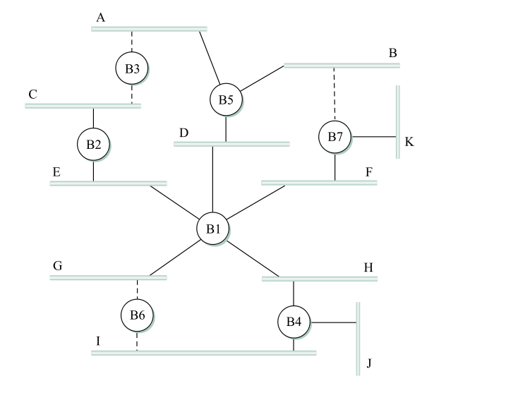
Here are the links not used, and why:
- B7 link to B: B7 and B5 are tied, but B5 has the smaller ID
- B6 link to I: B6 and B4 are tied, and B4 has the smaller ID
- B6 link to G: G connects directly to B1
- B3 link to C: B2 has a shorter path to B1
- B3 link to A: B5 has a shorter path to B1
Note that if a link is marked "not used", it is not used even in cases where it would be more efficient to use it. That is, traffic from F to B is sent via B1, D, and B5; it never goes through B7. IP routing, on the other hand, uses the "shortest path". To put it another way, all traffic goes through the root node, or along a path to/from the root node.
Virtual LANs (VLANs)
(Kind of skipped)
What do you do when you have different people in different places who
are "logically" tied together? For example, for a while part of the CS
dept was on the fourth floor of Lewis Tower, and part was on the
fourteenth floor of Corboy.
One approach is to continue to keep LANs local, and use IP routing
between different subnets. However, it is often convenient (printers
are one reason) to configure workgroups onto a single VLAN, by using
the concept of coloring. We
logically assign all nodes on the same subnet the same color, and
switches forward packets accordingly. That is, if S1 connects to red
machines R1 and R2 and blue machines B1 and B2, and R1 sends a
broadcast packet, then it goes to R2 but not to B1 or B2.
When the color of a port is known, nothing needs to be added to the
packet; the switch can keep track of who is on what VLAN. However,
switch-to-switch traffic must be additionally tagged to indicate the
source; imagine, for example, the previous S1 connected to S2 with
machines (red) R3 and (blue) B3. Traffic between S1 and S2 must be
tagged with the "color". The 802.1Q protocol is typically used for
this; a 32-bit "color" tag is inserted into the Ethernet header after
the source address and before the type field. The first 16 bits of this
field is 0x8100, which becomes the new Ethernet type field and which
identifies the frame as tagged.
Double-tagging is possible; this would allow an ISP to have one level of tagging and the customers to have another level.
3.1.2: virtual circuit switching
The road not taken by IP.
In VC switching, routers know about end-to-end connections. To send a
packet, a connection needs to be established first. For that
connection, each link is
assigned a "connection ID" (traditionally called the VCI, for Virtual
Circuit Identifier). To send a packet, the host marks the packet with
the VCI assigned to the host--router1 link.
Packets arrive (and depart) routers via one of several ports,
which we will assume are numbered beginning at 0. Routers maintain a
connection table indexed by <VCI,port> pairs. As a packet
arrives, its inbound VCI and inbound port are looked up, and this
produces an outbound <VCIout, portout> pair. The VCI field is then rewritten to VCIout, and the packet is sent via portout.
Note that typically there is no source address information included in
the packet (although the sender can be identified from the connection,
which can be identified from the VCI at any point along the connection). Packets are identified by connection, not destination. Any node along the path (including the endpoints) can look up the connection and figure out the endpoints.
Note also that each switch must rewrite the VCI. Datagram switches never rewrite addresses (though they do rewrite hopcount/TTL fields).
Example: construct VC connections between:
A and F
A and E
A and C
B and D
A--S1-----S2--D
| |
| |
B--S3-----S4----S5---F
| |
C E
I will use the following VCIs. They are chosen more or less randomly
here, but the requirement is that they be unique to each link. Because
links are generally taken to be bidirectional, a VCI used from S1 to S3
cannot be reused from S3 to S1 until the first connection closes.
A to F: A--4--S1--6--S2--3--S3--8--S5--1--F A to E via S2
A to E: A--5--S1--6--S3--3--S4--8--E
Note that this path went via S3, the opposite
corner of the square
A to C: A--6--S1--7--S3--3--C
B to D: B--4--S3--8--S1--7--S2--8--D
Demo: construct the <VCI,port> tables from the above.
end of class
The namespace for VCIs is small, and compact (eg contiguous). Typically
the VCI and port bitfields can be concatenated to produce a
<VCI,Port> index suitable for use as an array index. VCIs are local identifiers. (IP addresses are global identifiers.)
IP advantages:
- Routers have less state info to manage
- Router crashes and partial connection state loss are not a problem
- Per-connection billing is very difficult
VC advantages:
- connections can get resource guarantees
- smaller headers / faster throughput
- headers are small enough that virtual circuits are efficient even
for voice lines, where the data might be < 100 bytes. (TCP/IP
headers are a minimum of 40 bytes; voice data of 80 bytes would mean
33% header overhead)
3.1.3: source routing
Never used in the real world, but a conceptual possibility.