Comp 343/443 Fall 2011, LT 412, Tuesday 4:15-6:45
Class 1
History,etc, Packet switching. Layering.
Basic services: stream, request/reply
loss v delay tolerance
bandwidth v propagation delay
headers
Sketch of Ethernet, IP, routing, UDP, TCP, ports
Readings: 1.1, 1.2, 1.3, 1.5
Class 2
Basics of network programming: sockets
Ch 2: links
Readings: 1.4, 2.1, 2.2, 2.3, 2.4, 2.5
Class 3
Ch 2: encodings, checksums
Abstract sliding windows
Class 4
Ethernet physical level
Switched Ethernet; switch learning; datagram forwarding
//Demo of fixing port # to receive in wclient.java
Discussion of duplicated REQ, dallying, old-late-duplicates
Class 5
Datagram v Virtual Circuit
IP. fragmentation & routing..
subnets, including variable-sized masks
Distance-Vector intro
Class 6
Slow convergence for DV routing
ARP
TCP connection management; state diagram
connection creation for TCP
Building stateful connections on top of stateless layers
TCP: timewait, sequence numbering
Class 7IP address space exhaustion
Virtual Circuits
Source Routing
Framing; error detection/correction
ICMP, ping &traceroute
DHCP
Class 8
TCP timeouts
IP addressing models; CIDR
IP large-scale routing: geographical v provider
Midterm exam (~ 1 hour)
Class 9
TCP almost-to-Tahoe
TCP congestion avoidance
More routing issues: SPF, BGP, uses of BGP
Class 10
Lingering routing issues, NAT
TCP extensions, RPC, T/TCP, NFS
TCP Tahoe, Reno
ns simulation
Greediness of TCP
Fairness of TCP
cwnd = k / sqrt(P); TCP-friendliness
Class 11
multiple IP addrs is norm: web, localhost, lan, ...
HighSpeed TCP & the problems necessitating it
TFRC
Realtime protocols: RTP, VOIP
Timing:
PacketPairs
DecBIT
ECN - set one bit to indicate ECN-awareness, other to indicate congestion
RED - Random Early Drop
TCP Vegas
RSVP, IntegratedServices
Fair Queuing
RED, RIO
RPC: Sun, BLAST/CHAN
Error-CORRECTING codes
Class 12:
Class 13:
Class 14:
Week 1
General rules:
midterm, project(s), final
grad students will do an additional programming project
some students (those who have not completed Comp 170) will get an alternative assignment
READ: 1.1, 1.2, 1.3, and 1.5
READ: "A brief overview of networks", web page
READ: 2.1-2.3 (skim; this material is tricky)
Chapter 1
Network requirements:
- www/http: file transfers (bulk data)
- ssh/telnet, some database transactions: interactive exchanges
- VOIP (Voice (telephone) over IP)
- network video, 5 250x200 frames/sec, 4 bytes/pixel = 1mB/sec!
(Well, we can probably manage with 1 byte/pixel. Still, with video
compression at 10-30-fold, compression becomes part of the network
infrastructure.)
1.2.1: connectivity v links
- links: point-to-point v multiple-access
- you need links to get connectivity, though they alone don't guarantee connectivity; you may also need switches.
Connectivity also requires switching/routing, usually via a store&forward mechanism.
- The cloud model: connectivity
and switching work at different levels of abstraction. In the cloud, we
ignore the implementation of connectivity (ie switching). Connectivity
requires some mechanism
(global?) of addressing.
- internerconnected (internetworked) clouds
- Addressing and Routing together
- unicast v multicast/broadcast
1.2.2: sharing
- circuit switching: a separate wire for each connection. Not very practical, but it is still
used for POTS (Plain Old Telephone Service) for many residences. And
the telecom world is full of "DS0 channels", that is, reserved 64kbps
channels with minimal delay (in particular, minimal packet fill delay; see below).
- packets & packet switching: packets carry a destination address.
- maximum packet size as a sharing requirement (max size also plays role in error handling; ok to lose one packet)
- packet switching also accomodates bursty traffic rather well: an idle station doesn't consume any link resources.
Packet switching automatically implements multiplexing (sharing) on links; the demultiplexor is the destination address.
Port numbers allow demultiplexing of multiple streams to same destination host.
other sharing strategies:
- STDM: time slicing (popular with voice, where per-connection
bandwidth is fixed). Phone network digital DS lines and Sonet optical
lines are built around STDM, with each connection getting 1 byte every
1/8000 sec.
- FDM: like cable-tv channels; not as efficient; sort of obsolete but note that cable modems may use this
Some of these still appear in cellular telephony (where they still make
sense); GSM is a form of STDM; the old AMPS was a form of FDM.
switch issues
- store-and-forward (switching/packetization) delay
- queuing, congestion, drop, FIFO, droptail, random-drop, round-robin
- Sidebar: LANs, MANs, SANs, WANs
Example of store-and-forward delay: one packet sent along a path A-----S-----B.
The bandwidth of each link is 1mbps; the packet side is 1kbit, so a
packet takes 1ms to traverse a link.
Store-and-forward delay: the packet takes a total of 2
ms to traverse the two links. That is, S cannot begin retransmitting
the packet to B until it has completely arrived. We are ignoring
propagation time here. (Some switches did at one time implement cut-through,
meaning that retransmission on the outbound link began before the
packet had fully arrived. In practice, this turns out not to be as
useful as one might think.)
There is another form of packetization delay related specifically to
voice (and to some other real-time applications where bytes are
generated at a specific rate). Voice is generated at 8 bytes/ms
(64kbps). The time to fill a 1000 byte packet is thus 125 ms; if you
start speaking, your voice cannot even leave the phone for 125 ms. I sometimes call this fill delay. The source is the only point where this delay occurs; packetization delay at internal switches is much smaller. However,
there is a second 125 ms delay at the other end. Generally speaking,
VOIP protocols use much smaller packet sizes (eg 160 bytes / 20 ms).
1.2.3: common services
Reliable bi-directional channel: this is what the TCP protocol provides.
just read and write; network fixes packet loss and reordering
FTP v NFS: file transfer v filesystem sharing
FTP & Telnet are obsolete, but are still the canonical examples.
New replacements: SFTP/scp, ssh
Some comparisons:
- bursty v steady, reliable v loss-tolerant
- request/reply v message stream
- delay-indifferent v delay-sensitive
delay-sensitive, loss-intolerant is very bad!
voice/video requirements
Voice requires 64,000 kbps (1 byte every 1/8000 sec) (at least in the US). However, we also need uniform propagation delay. The statistical variation in delay is known as jitter.
Also, the propagation delay must be relatively small; if the delay is,
say, 100ms, then the round-trip "turnover time" is 200ms, which means
that whenever one person stops talking and the other starts, a delay of
200ms will be perceived. That value is large enough to be objectionable.
Video simply requires greater bandwidth, in addition to the delay issues. However, note that for one-way video (broadcast), the propagation delay doesn't really matter at all.
Reliability
Four things that can go wrong at the hardware level.
- bit errors: typical rate 1 in 107
- bit-burst errors, eg due to a refrigerator turning on
- packet drops (eg in queues)
- backhoes, switch failure and other catastrophic damage
What are some things that can go wrong at the software level?
1.3: Layering & Protocols
headers
HHP - host-to-host protocol (eg IP)
RRP - request-reply protocol (this could be TCP or UDP)
MSP - message-stream protocol
Layering and architecture (P&D 1.3) (a method of abstraction)
Levels: 5-level TCP/IP model, 7-level ISO model, summary of levels
- Physical (e.g. physical ethernet)
- Network interface (eg logical ethernet) (small)
- Network (machine endpoints; routing & delivery issues) (BIG)
- Transport (reliable streams; process endpoints)
- Application (OSI divides this into Application/Presentation/Session,
where Presentation includes compression, byte conversions, encryption,
and Session includes local echo, buffering, access rights, billing,
portmap)
HHP/RRP/MSP layers; protocol graphs, encapsulation (1.3)
See Figure 1.14 for an IP graph
What would RRP be? Possibly UDP, but also possibly HTTP (on top of TCP): this supports GET requests and responses.
What would MSP be? TCP is the "canonical" answer, but it might also be RTP (Real-Time Protocol), on top of UDP. The reason for not using TCP is that TCP waits for lost packets to be retransmitted; real-time applications like interative voice/video simply need to keep moving.
Multiplexing / Demultiplexing
This is handled above the HTH level.
Network Issues
These are a few of the things to consider.
- Robustness & connectedness - can everyone reach everyone else?
-
performance - # of users, demand for bandwidth
-
Internetworking between different protocols (TCP/IP, NetBios, SNA, ...)
-
Scalability -- can a network grow?
-
handling growth of the Internet
-
Authentication and privacy
-
How can one endpoint tell if someone is who they claim to be?
-
trusted hosts v. passwords v. public-key systems
-
interception, modification, spoofing
-
Gateways and routing - how to handle this efficiently
-
management - How can managers detect & fix problems; plan for growth
-
continuous v. bursty traffic
-
options: quality-of-service, real-time performance, multicast, acctg.
Section 1.5 (parts may be deferred as necessary)
bandwidth v delay (esp propagation delay)
delay: propagation + bandwidth (transmit) + queue
In this view, switching delay is being counted as bandwidth delay.
basic diagrams:
- one packet, no switching, with propagation delay and bandwidth delay
- one packet through a switch
- three smaller packets through a switch
- prop delay >> bandwidth delay
implications for protocols:
bandwidth-limited: easy to design for; extra RTTs don't cost much
delay-limited, eg to moon (0.3 sec RTT), jupiter (1 hour RTT): Here the protocol designer must focus on minimizing extra RTTs.
cross-continental US roundtrip delay: ~100ms (speed 200 km/ms in
cable, ~10,000 km cable route (6000 mi). The cable path is probably a
lot shorter, but there's also likely to be queuing delay.)
At 1.0 Mbit, 100ms is 10K or so.
At 1.0 Gbit, 100ms is 10,000K.
From my house, I used to use satellite internet, which has a propagation delay of ~600 ms!
100 RTTs v 101 RTTs: not significant
1 RTT v 2 RTTs: very significant
Latency = propagation + transmit (bandwidth) + queue
Propagation = Distance / speed_of_light
Transmit = Size / Bandwidth
When dealing with "large-scale" networks (eg the internet), to good approximation most of the delay is propagation, and so
latency and bandwidth are effectively independent. Note that when
propagation delay is small, though, the two are interrelated.
Delay × Bandwidth (usually RTT delay), and pipe size: this is how
much we can send before we hear anything back, or how much is "pending"
in the network at any one time. Note that, if we use RTT instead of
one-way time, then half the "pending" packets will be returning
acknowledgements.
1 ms x 10 mbps = 1200 bytes ~ 1 packet
100 ms x 1.5mbps = 20 K
100 ms x 600 mbps = 8 MB!
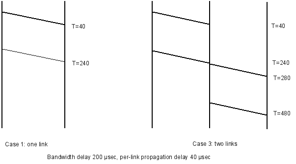
Example: Consider a simple network with the following properties:
-
propagation delay 40µsec
-
bandwidth is 1 byte/µsec (1mB/sec, 8mbit/sec)
-
We are sending 200-byte packets (200 µsec bandwidth delay)
Case 1: A------------B
Total time: 240 µsec = 200 µsec + 40 µsec
Case 2: A---------------------------------------B, prop delay 4ms
Total time: 4200 µsec = 200 µsec + 4000 µsec
Case 3: A------------R----------B, each link prop delay 40 microsec
Total time: 480 µsec = 240 + 240
Case 4: same as 3, but send two 100-byte packets
Total time: 3*100 + 2*40 = 380 µsec
Note that sending two smaller packets is faster than one large packet.
This is a very real effect, and has sort of put an end to interest in
IP "jumbograms". As an extreme case, the (now-seldom-used) ATM protocol
(intended for both voice and data) uses packets with 48 bytes of data
and 5 bytes of header.
Sketch of each layer in TCP/IP
Ethernet: basic LAN.
multiple-access coax versus hubs (not switches, not yet)
everything-is-really-broadcast
Network Interfaces & physical addrs; address uniqueness; addresses assigned at the factory
privacy implications; bandwidth implications
collisions
CSMA/CD
packet address format: 6 bytes
b'cast address: ff:ff:ff:ff:ff:ff
uses of b'cast
multicast
Switched Ethernet: changes lots of the sharing rules; once the
switches have acquired all the destinations, each packet takes the
precise path to its destination. (Paths are unique because Ethernet
does not allow alternative routes, that is, cycles.)
Other links
DSL
Cable modem
Satellite
DS1 = T1 = 1.544 Mbps = 1544 Kbps = 24 * 64 Kbps + 8Kbps framing
basic voice: 8KBps. T1 = 24 voice bytes + 1 framing bit
DS3 = T3 = 44.736Mbps
Wi-fi
Other wireless links (Wi-Max, proprietary)
Optical (SONET)
STS-1: 51.840 Mbps, aka OC-1
STS-3: 155.520 Mbps = 3*STS-1, aka OC-3
STS-12: 622.080 = 12*STS-1
STS-48
STS-192, 9.9 Gbps
...
STS-3072, 159 Gbps
STS = synchronous Transport Signal
ATM: Asynchronous trannsport mode
Ethernet switching
forwarding tables
one entry for every end node (eventually)
fewer collisions (what replaces them?)
The general strategy here is called datagram forwarding, though the particular point of Ethernet switching is that we need a table entry for every host address.
An important issue with switched Ethernet is that each switch must
acquire the next-hop information (output-port information) for every destination.
If a switch is handling traffic for 10,000 hosts, it must have 10,000
entries. IP, on the other hand, allows some substantial consolidation
of the forwarding table.
IP
Net/host portions of addresses
Administratively assigned addresses, so that all hosts on the same network can be given the same net portion.
IP delivers to destination network; that network must correspond to a physical LAN that can complete the delivery
CLASSIC IP: classes A, B, C (deprecated)
IP header v Ethernet header (ignore fields of IP header for now)
What an IP ROUTER does
Extraction of Dest_net
Routing tables
Routing table size
IP has no broadcast (well, there is a limited form of IP broadcast, basically intended for your LAN only)
best-effort delivery: if the packet is lost (eg through router
queue overflow), the IP layer is not responsible for replacing it. Nor
does the IP layer handle acknowledgements.
Example of delivery through a router
IP routing algorithm:
Extract destination_network from packet, and decide if this router connects to that network
- YES: local delivery; use LAN to deliver
- NO: look up destination_network in forwarding table and send to the next_hop
Significance of administrative assignment
: the destination_network
part of each IP address represents something about the host's location.
Compare to Ethernet switch, with per-host forwarding table
A
B
C
D E F
|
| |
| |
|
+----+----+--S1-------S2------S3----+----+----+
200.0.0
200.0.1
Ethernet forwarding: S2 has to maintain entries for A,B,C,D,E,F
IP forwarding: S2 has two networks to maintain: 200.0.0/24 and 200.0.1/24
Goal of smaller routing tables
Two benefits to IP:
- allows interconnection ("internetworking") of incompatible LANs
- routing strategy is SCALABLE: works well with very large Internet
For the past ~15 years, IP addresses have not used the old Class A/B/C
mechanism. Separation into network and host portion is still done, but
is now "floating". When you buy a block of IP addresses, you get the
network portion, or network prefix. The length of that portion in bits is your prefix length, and is usually appended to the address prefix itself following a slash, eg
10.0.0.0/8
147.126.0.0/16
19.192.0.0/10 (192 = 1100 0000)
If we don't care about the prefix, we omit it:
"Class A's are /8 address blocks; class B's are /16"
"It cost me $2,000/year to get a /18!"
Note that the IP protocol has not been changed, so there is no place in the IP header to specify this prefix length.
- This means that routers must use some other way to divide addresses into net & host portions (typically, by keeping track of the prefix length for each prefix it is configured to know about)
- This means that the routers may use different prefix lengths for the same address, at different points of the routing infrastructure.
UDP
User Datagram Protocol: simple header, no retransmission or acknowledgement features
UDP is a very simple extension to IP; it basically just adds port numbers for application-level multiplexing, and a checksum over the data.
Socket
= <host,port>; this acts like a mailbox address in that anything
sent to it will be delivered to the receiving application (typically
through some sort of socket handle in the underlying OS)
demo of stalkc, stalks (defer)
demo with two clients
TCP
Adds:
-
stream-oriented connection: no application packetization
-
reliability
-
port-number mulitplexing like UDP
Also: uses sliding-windows to establish a maximum number of packets en route at any one time, per connection.
Later, TCP sliding-windows was adapted to manage congestion.
You connect TO a socket = ⟨host,port⟩ (this is actually a "listening" socket, not a "connected" socket.)
Everything sent on that connection goes to same place.
⟨host,port⟩ doesn't received directly;
only "connected_sockets" receive data; you can only receive data from the endpoint to which you are connected.
TCP semantics are more like "telephone" semantics, for a room with
dozens of phones all answering to the same phone number (eg for
telephone sales). Each remote phone's data goes to, say, 1-800-LOYOLA1,
but it is routed by the phone switch to the correct phone based on what
phone it came from. That way, each remote phone has its own connection.
Uses:
TCP: telnet, http/ftp
UDP: voice/video. Why?