Comp 353/453: Database Programming, LT 410, 4:15 Tuesdays
Week 6
Tutoring: Faraz Khan, Wed 5:00-7:00 pm, fkhan10@luc.edu.
Midterm: March 22
Entity-Relationship modeling
Last week we looked at entities,
which represent concrete objects (employees, parts) and also abstract
objects that still have a strong real-world you-can-point-to-it
existence: courses, departments, projects, sections.
At this early stage, we allowed entity attributes to be composite or
computed or multi-valued; all of these will eventually be handled in
specific ways as we translate into SQL.
In the class example, I listed dept as an attribute of EMPLOYEE, and argued that because dept
represented an instance of another entity (DEPARTMENT), we would have a
foreign-key constraint on EMPLOYEE.dept, referring to
DEPARTMENT.dnumber.
Note, however, that we could have instead listed employees
as a multi-valued attribute of DEPARTMENT. One reason we did not do
this is that we do want to minimize the use of multi-valued attributes,
but this arrangement would have been an option. Later, we even could implement this second approach by adding an attribute dept to the EMPLOYEE table (the table, not entity).
We actually could have both forms, but we would need to understand the constraint that if employee e is in the employees multi-valued attribute for DEPARTMENT d, then department d must be be the value of the EMPLOYEE e's dept attribute. That is, the dual attributes would have to be inverses.
As for naming entities, a common practice (used by E&N) is to name
them with singular nouns. Nouns because they should represent things;
singular for the individual objects. Eventually we will have a table of
employees, plural, but we call it EMPLOYEE to represent what entities it contains.
Weak entities
The usual definition of a weak entity is that it is an entity that does
not have key attributes of its own. I also claimed that the DEPENDENT
entity had attributes name, birth_date, sex, relationship, and
employee. Because <name, employee> is in fact a key for
DEPENDENT, I argued that the employee attribute is really a reference
to another entity, and we really want "atomic" attributes here.
This isn't quite correct. At the entity analysis phase, we should
instead view the attributes of a dependent as (name, bdate, sex,
relationship), with the attribute employee
coming along at a later stage of the process. After all, the EMPLOYEE
is really someone else, not an attribute of the DEPENDENT person itself
(at least not in the same sense as bdate,age,etc). There is, instead, a
relationship between the DEPENDENT entity and EMPLOYEE; this relationship is the identifying relationship for DEPENDENT.
In general, during the design process, the statement that "dependents do not have a key" is subject
to interpretation; we can always declare that the associated employee's
SSN is part of the key. However, the point is that dependents do not
have a "natural" key that is an attribute of the dependent itself.
There is a total participation constraint between DEPENDENT and
EMPLOYEE; every DEPENDENT must be connected to some EMPLOYEE. As the
book points out, however, every DRIVERS_LICENSE is associated with some
PERSON, but the DRIVERS_LICENSE entity does in fact have its own key:
the drivers_license_number.
The way that DEPENDENT could become a strong entity is if we added its own
key: dependent_ssn. But typically the SSNs of dependents are not known
(minor dependents may not even have SSNs), so we choose not to
implement the database this way.
The DEPENDENT entity does have a partial key: the attribute name, which, together with the associated EMPLOYEE object, does define a key.
We could also represent dependents as a multi-valued, composite attribute of EMPLOYEE.
Fig 7.8 lists all the entities.
Relationships
Initially we arrive at Fig 7.8, with four entities: DEPARTMENT,
PROJECT, EMPLOYEE, DEPENDENT. Note that Works_on here is shown as an
EMPLOYEE attribute; it could also be represented as a PROJECT
attribute. How are we representing department membership? Who works on what? Who is in charge of what projects?
Note some of the attributes in figure 7.8 refer to other entities.
These are our first relationships; these will likely end up translated
into foreign key constraints.
A relationship formally is a
set of ordered tuples ⟨e1,e2,...,en⟩ where each ei is a member of
entity Ei. Some entities here may simply be attributes (eg the hours attribute of the WORKS_ON relationship ⟨employee,project,hours⟩.
The tuples in a relationship must each have a clear meaning to the
application. Relationship names are usually verbs, and should make
sense "left to right" (and sometimes top to bottom). That is, we would
prefer the relationship name supervises because it fits in with
SUPERVISOR----- supervises ------EMPLOYEE
We could also use
EMPLOYEE ----- reports_to ------ SUPERVISOR
Most relationships are binary (possibly with added attributes); ternary and higher-degree relationships are less common.
At this stage, we may model a relationship as a (typically multivalued)
entity attribute; consider again how we modeled WORKS_ON in Figure 7.8.
When a relationship involves multiple entities, we can assign a role name
to each entity. Commonly this is just the name of the entity (eg
EMPLOYEE), but in relationships between an entity and itself (so-called
recursive relationships), we
have to use different names. Consider the example of the SUPERVISES
relationship.
Example: fig 7.11; note that the righthand SUPERVISION
oval contains references to pairs of entities in the lefthand EMPLOYEE oval.
For entities, it is often the case that we elect to use synthetic keys:
arbitrarily generated "ID numbers". This makes sense for departments
and employees. Relationships, however, typically have a natural key
consisting of one primary key from each entity; using synthetic keys
(eg order numbers) should stand out. A good example of this is the
GRADE_REPORT table, indexed by student_number and section_identifier
(and with attribute grade).
How should we model SECTION in the school database? We did model it as
an entity, but could we model it as a ternary relationship between
course, semester, and instructor? No, if we allow an instructor to
teach two sections of the same course in the same semester.
What about an INVOICE? This consists of a number of ITEMs, each with
quantity, ordered by a single CUSTOMER. We can create a relationship
ORDERS between CUSTOMER and ITEM, but an invoice is more than that. If
a customer places multiple orders on the same day, the customer likely
expects them to remain different. So instead we would have an entity
for INVOICE, with attributes invoice_number (synthetic), and date, and
customer, and then create a relationship ORDERS between INVOICE and
ITEM, with attributes for price and quantity:
invoice
|
item
|
price
|
quantity
|
1002
|
37
|
$5
|
6
|
1002
|
59
|
$3.45
|
2
|
1003
|
101
|
$1300
|
1
|
Cardinality
Binary relationships can be classified as 1:1, 1:N, N:1, or M:N. In the
WORKS_FOR relationship, between DEPARTMENT and EMPLOYEE, this is 1:N. Each
employee works for 1 department, but a department can have multiple
employees. (Again, the 1 here in 1:N represents a constraint; the N
represents no constraint. It is not actually required that all
departments have multiple employees.)
The MANAGER relationship is 1:1 (though see the note): every dept
has one manager and vice-versa. This is a 1-1 relationship between
EMPLOYEE and DEPARTMENT. Note that most employees are not managers;
this does not change the fact that no employee manages two departments.
See Fig 7.12 for a diagram representing this.
Note: that the MANAGER relationship is 1:1 expresses a business rule:
no employee manages more than one department, and no department has two
managers. The latter is pretty universal; the former, while common, is
not.
Many relationships are 1:N (one-to-many):
DEPARTMENT ----1--- employs ----N----- EMPLOYEE (or employee works_for department)
EMPLOYEE -----1----- supervises ----N------EMPLOYEE (boss is on left side)
DEPARTMENT ----1---- controls-----N------PROJECT
Think of "1 department = N employees"; the 1 goes on the side that the other
entity can have only 1 of. The 1 goes on the "larger" unit: a
department is made of N employees, a boss supervises N employees, a
department controls N projects.
See Fig 7.9.
The supervises relationship is "recursive" (a better word, used in the
UML community, is "reflexive"). See figure 7.11 for a diagram.
The WORKS_ON relationship is M:N.
Similarly, the enroll relationship is M:N
STUDENT -----M----- enrolls ----N----SECTION
A section may have several students; each student may enroll in several sections.
See fig 7.13.
What do we do if, after we've gotten started, we decide that the location attribute of a DEPARTMENT should be multi-valued? We can model multi-valued attributes as relationships instead:
DEPARTMENT ----N----is_located_at-----M----LOCATION
Clearly, we would not want this to be 1:M, which would mean that a
location could be used by only one department. If we do decide that
departments have single locations, we go back to an N:1 relationship:
DEPARTMENT ----N----is_located_at-----1----LOCATION
Participation constraints on relationships
Suppose every employee must work for some department. Then the WORKS_FOR relationship involves total participation of the EMPLOYEE entity. The MANAGES relationship involves partial participation of the EMPLOYEE entity, at least as far as supervisors are concerned.
We represent total participation by a double line, and partial by a single line.
Relationships can have attributes; eg hours of WORKS_ON or grade for the GRADE_REPORT table.
As was described above, entities usually have a single (possibly composite) key; entities are often given a synthetic
key (ie an employee_id or student_number). Relationships typically have
a key with as many attributes as the degree of the relationship.
Synthetic keys are often awkward for these.
The key to a relationship should be a composite of the keys to each
entity. Otherwise the relationship is not just about the two entities
involved.
Note that synthetic keys work very well for joins.
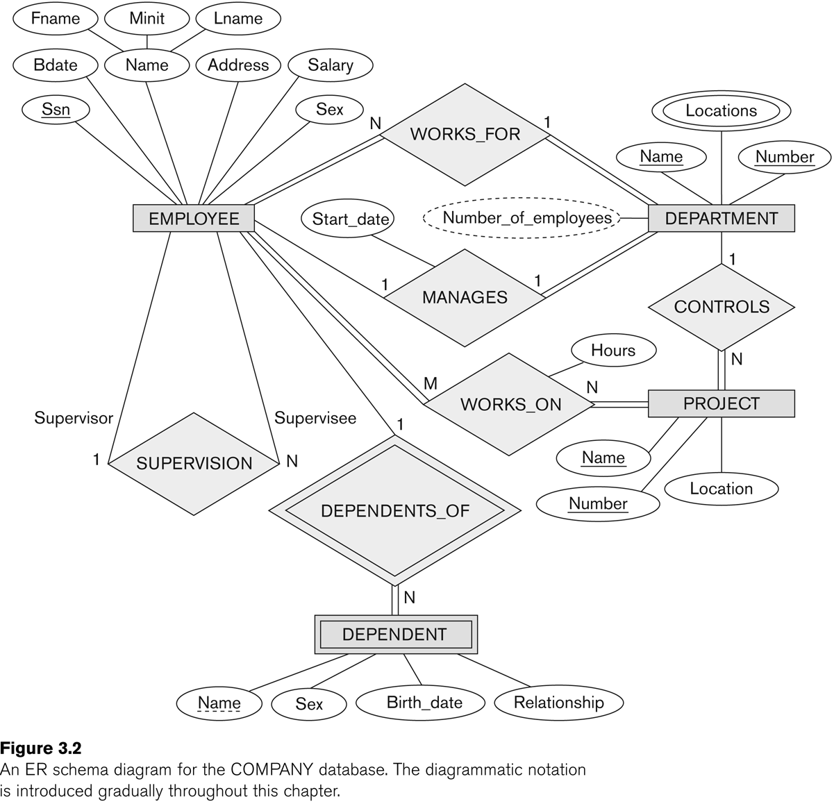
Now we should be able to go through Figure 7.2 (E&N p 204) in
detail. The relationships are supervises, works_for, manages, controls,
works_on, and dependents_of. Note that the name "supervision" is
awkward; it is not clear who is supervising whom. As a result, the
entity links need annotation with the role names "supervisor" and
"supervisee". However, such annotation is often a good idea for clarity.
(The figure below was Fig 3.2 in an earlier edition of E&N; it is Fig 7.2 in the 6th edition.)
Sometimes, as we rethink things, an attribute can be changed to a
relationship, or vice-versa. Sometimes an attribute may be promoted to
an entity, particularly if it was used in several other entities, in
which case we may also add a relationship to those other entities.
Relationship attributes can sometimes be moved to entities. For a 1:1
relationship, the attribute can be moved to either entity. For a 1:N
relationship, the attribute can be moved to the N side. Consider the
earlier examples:
DEPARTMENT ----1--- employs ----N----- EMPLOYEE attribute: start_date, etc
EMPLOYEE -----1----- supervises ----N------EMPLOYEE attribute: review_date
DEPARTMENT ----1---- controls-----N------PROJECT attribute: project_budget_num
Sometimes we have entity attributes that need to be translated into
relationships. See Section 7.6. We would move manager information from
the DEPARTMENT entity to the MANAGES relationship. We started out with manager as an attribute of departments, but later realized that there was a relationship involved because two entities were involved: DEPARTMENT and EMPLOYEE. This suggests the need for a relationship.
We would move controlling-department information from the PROJECT
entity to the CONTROLS relationship. We would remove department,
supervisor, and works_on from EMPLOYEE. Note that some of these will
eventually be added back. At this point, we should have eliminated most
multi-valued attributes.
ER diagram for the STUDENT database
Entities: student, course, section
(min,max) annotation
Instead of labeling lines connecting a relationship to an entity with
1, M, or N, we can also use a (min,max) notation, meaning that each
entity e in the entity set E must participate in at least min entries
of the relationship, and at most max. If min>0, the participation is
total; min=0 means partial participation. The max is denoted N when we
mean it is allowed to be >1.
Note that a 1-N relationship would have the values reversed using the (min,max) notation:
DEPARTMENT ----1--- employs ----N----- EMPLOYEE
DEPARTMENT ---(1,N)--- employs --- (1,1)----- EMPLOYEE
Example: Fig 7.15
UML diagrams
See Figure 7.16. UML diagrams have space for operations,which
in the world of databases we're not much concerned about. The big boxes
are for entities; relationships have been reduced to boxes that
annotate links. A (min,max) notation is used, but the label goes on the
opposite entity.
UML relationships (actually, ER relationships as well) may either be of association or of aggregation. The latter implies a collection, eg of employees into one department.
How do we translate this to tables?
We'll go into more detail later, but for now, note that a 1:1 relationship can be represented as an attribute of either entity. A 1:N relationship can be modeled as an attribute of one of the entities (the entity on the side of the N). M:N relationships must get their own table.
Ternary and other higher-degree relationships
Consider the
SUPPLY relationship on a supplier s, project j, and part p. The tuple
⟨s,j,p⟩ is included if s supplies part p for project j.
We might try to model this with three binary relationships,
SUPPLIES(s,j), CAN_SUPPLY(s,p), and USES(j,p). It is true that if
⟨s,j,p⟩ is in SUPPLY, then ⟨s,j⟩ is in SUPPLIES, ⟨s,p⟩ is in
CAN_SUPPLY, and ⟨j,p⟩ is in USES. But the converse is not true.
See Fig 7.17.
As for binary relationships, a ternary relationship key is a triple of keys from each participating entity.
Ternary relationships can be problematic, and so we often include corresponding binary relationships.
One approach is to model a ternary relationship as a weak entity, with
three identifying relationships (Fig 7.17(c)). Or we can give SUPPLY a
synthetic key, supply_id, and then relate it to SUPLIER, PROJECT, AND
PART by binary relationships.
The next example is OFFERS, for a school database; see Fig 7.18;
⟨i,s,c⟩ belongs to OFFERS if INSTRUCTOR i teaches COURSE c during
SEMESTER s. Again, the binary projections fail to adequately model the
ternary relationship. E&N suggest that if one of the binary
relationships is 1:1 (eg if the CAN_TEACH(i,c) relationship is 1:1),
then this does work, but that is seldom if ever the case.
Actually, in a real school database one would not use OFFERS, one would
use SECTION. The latter would likely be an entity, complete with
synthetic key section_id.
Ternary relationships can have cardinality tags, like binary
relationships, but they are not as straightforward. For the SUPPLY
relationship, suppose each project,part pair (j,p) can have only one
supplier. Then we might put a 1 on the SUPPLIER link. But it might also
be the case that each project j uses a unique supplier,part pair (s,p)
(that is, each supplier can supply only one part to each project). We
now have an unrelated 1 on the PROJECT link.
The (min,max) relationship is more straightforward: E------(m,M)-----R
means that for each e in E, there are at least m tuples involving e in
R, and at most M.
ER-to-relational mapping
How do we build a database schema from an ER diagram?
Step 1: regular entities
We define a table for each non-weak entity. We use all the leaf
attributes; composite attributes are represented by their ungrouped
components. Keys are also declared. Attributes that were earlier pushed
into relationships are not yet included.
Step 2: weak entities
We create a table for each weak entity, adding the keys for the owner
entity type (or types) (this would mean employee ssn), and adding a foreign key constraint to the owner-entity table.
We are likely to use the CASCADE option for drop/updates: if an
employee ssn is updated, then the dependent essn must be updated, and
if an employee is deleted, then all the dependents are deleted too.
Step 3: binary 1:1 relationships
Let S and T be the participating entities to 1:1 relationship R. We
pick one of the two -- say S -- and add to S a column that represents
the primary key of T, and all the attributes of R.
It is better to choose as S the entity that has total (or at least
closer to total) participation in R. For example, the manages
relationship between departments and employees is 1:1, but is total
only for DEPARTMENT, and is nowhere near total for EMPLOYEE. Thus, we
add a column manager to DEPARTMENT. However, adding a column manages to EMPLOYEE would work.
We also add a foreign key constraint to S, on the new attribute, referring to the primary key of T.
One alternative is to merge S and T into a single relationship; this makes sense only if both have total
participation in R. This means that S and T each have the same number
of records, and each record s in S corresponds to exactly one t in T.
A third alternative is to set up a table R containing <sk,tk> key pairs.
Step 4: binary 1:N relationships
Let us suppose S---N---R---1---T. We now add T's key to S as an attribute with foreign-key constraint. We must add T's key to S; we cannot do it the other way around. In the relationship
DEPARTMENT ----1--- employs ----N----- EMPLOYEE
we would have S be EMPLOYEE; we would put a dno column in EMPLOYEE (why can't we add an essn column to DEPARTMENT?)
An alternative is the <sk,tk> keypair table. This might be more
efficient if only a few s in S participate in the relationship;
otherwise we would have many NULLs in the T-column of S.
Step 5: binary M:N relationships
Here we must create a table R of tuples including the key of S (sk), the key of T (tk), and any attributes of R; we can not
push the data into either S or T. Call the new table also R (note that
E&N call it S). The sk column of R should have a foreign key
constraint referring to the key column of S, and the tk column of R
should similarly have a foreign key constraint to the key column of T.
The WORKS_ON table is a canonical example; so is the GRADE_REPORT table.
Again we would likely to use the CASCADE option for deletion or update of records in the participating entities S & T.
Step 6: multivalued attributes
If we have any left, they must be moved into their own tables. For example, if employees can have several qualifications
(eg degrees or certifications), we would create a table QUALIFICATION
with two columns: essn and qualification. The DEPT_LOCATIONS table is
similar. Again, we would have an appropriate foreign key constraint
back to the original table.
Step 7: higher-degree relationships
These are handled like binary M:N relationships.
Another note on foreign-key constraints
I said earlier that if table T had an attribute that was an entity of
type S, then we would add a foreign key constraint to T referring to S.
That's not literally what is outlined here, but the two approaches are
equivalent: earlier we should have taken any T-attributes of type S and
created a relationship. We do this under the rule that whenever we have
entity attributes involving two entities, we should push the attribute
into a new relationship.