Comp 353/453: Database Programming, Corboy
L08, 4:15 Mondays
Week 6, Feb 25
Read in Elmasri & Navathe (EN)
- Chapter 4: Basic SQL
- Chapter 5: More-complex SQL (section 5.1 especially)
- Chapter 7: ER models and diagrams
- Chapter 9: ER-to-relation mapping
The midterm will be the second half of the March 18 class.
Homework 1:
4.7: parts 4 and 6 were the ones for which the best argument can be made against
on delete cascade:
4. BOOK_COPIES.Branch_id
⟶ LIBRARY_BRANCH.Branch_id
6. BOOK_LOANS.Branch_id
⟶ LIBRARY_BRANCH.Branch_id
If a library branch closes, this is a special situation, and arguably you
want to resolve the book_copies and book_loans issues before
allowing the branch to be deleted; this would suggest on delete
restrict (I called it on delete reject on many
of the homework papers), which means to disallow the deletion. Another
option might be the set null / set default choice.
Entity-Relationship modeling
Here's a summary for the construction of entities:
- Look for the "concrete" objects in the problem domain
- List the attributes of each entity.
- Break compound attributes down into atomic attributes
- Attributes can, at this stage, be multivalued
- Indicate the (single-attribute) key for each entity
- Do not use other entities as
attributes; model this instead at the relation stage
- This may leave some entities ("weak" entities) without a complete key.
Just mark them as such
- Weak entities will be tied to some other entity through the defining
relationship.
Relationships
Initially we arrive at Fig 7.8, with four
entities: DEPARTMENT, PROJECT, EMPLOYEE, DEPENDENT. Note that Works_on here
is shown as an EMPLOYEE attribute; it could also be represented as a PROJECT
attribute. How are we representing department membership? Who works on what?
Who is in charge of what projects?
Note some of the attributes in figure 7.8
refer to other entities. These are our first relationships; these will
likely end up translated into foreign key
constraints.
A relationship formally is a set of
ordered tuples ⟨e1,e2,...,en⟩ where each ei
is a member of entity Ei. Some entities here may simply be
attributes (eg the hours attribute
of the WORKS_ON relationship ⟨employee,project,hours⟩.
The tuples in a relationship must each have a clear meaning to the
application. Relationship names are usually verbs, and should make sense
"left to right" (and sometimes top to bottom). That is, we would prefer the
relationship name supervises
because it fits in with
SUPERVISOR----- supervises
------EMPLOYEE
We could also use
EMPLOYEE ----- reports_to
------ SUPERVISOR
Most relationships are binary (possibly with added
attributes); ternary and higher-degree relationships are less common (and
less tractable).
In early stages we may model a relationship as a (typically multivalued)
entity attribute; consider again how we modeled WORKS_ON in Figure
7.8.
When a relationship involves multiple entities, we can assign a role
name to each entity. Commonly this is just the name of the entity
(eg EMPLOYEE), but in relationships between an entity and itself (so-called
recursive relationships), we have to
use different names. Consider the example of the SUPERVISES relationship.
Example: fig 7.11; note that the righthand
SUPERVISION oval contains references to pairs
of entities in the lefthand EMPLOYEE oval. (Which numeric label is used to
indicate the supervisor?)
For entities, it is often the case that we elect to use synthetic
keys: arbitrarily generated "ID numbers". This makes sense for
departments and employees. Relationships, however, typically have a natural
key consisting of one primary key from each entity; using synthetic keys (eg
order numbers) should stand out. A good example of this is the GRADE_REPORT
table, indexed by student_number and section_identifier (and with attribute
grade).
How should we model SECTION in the school database? We did model it as an
entity, but could we model it as a ternary relationship between course,
semester, and instructor? No, if we allow an instructor to teach two
sections of the same course in the same semester.
What about an INVOICE? This consists of a number of ITEMs, each with
quantity, ordered by a single CUSTOMER. We can create a relationship ORDERS
between CUSTOMER and ITEM, but an invoice is more than that. If a customer
places multiple orders on the same day, the customer likely expects them to
remain different. So instead we might choose to have an entity
for INVOICE, with attributes invoice_number (synthetic), and date, and
customer, and then create a relationship ORDERS between INVOICE and ITEM,
with attributes for price and quantity:
invoice
|
item
|
price
|
quantity
|
1002
|
37
|
$5
|
6
|
1002
|
59
|
$3.45
|
2
|
1003
|
101
|
$1300
|
1
|
Cardinality
Binary relationships can be
classified as 1:1, 1:N, N:1, or M:N. In the WORKS_FOR relationship, between
DEPARTMENT and EMPLOYEE, this is 1:N. Each employee works for 1 department,
but a department can have multiple employees. (Again, the 1 here in 1:N
represents a constraint; the N represents no constraint. It is not actually
required that all departments have multiple employees.)
The MANAGER relationship is 1:1 (though see the note): every dept has one
manager and vice-versa. This is a 1-1 relationship between EMPLOYEE and
DEPARTMENT. Note that most employees are not managers; this does not change
the fact that no employee manages two departments. See Fig
7.12 for a diagram representing this.
Note: that the MANAGER relationship is 1:1
expresses a business rule: no
employee manages more than one department, and no department has two
managers. The latter is pretty universal; the former, while common, is
not.
Many relationships are 1:N (one-to-many):
DEPARTMENT ----1--- employs ----N-----
EMPLOYEE (or employee works_for department)
EMPLOYEE -----1----- supervises ----N------EMPLOYEE (boss
is on left side)
DEPARTMENT ----1---- controls-----N------PROJECT
Think of "1 department = N employees"; the 1 goes on the side that the other entity can have only 1 of. The 1
goes on the "larger" unit: a department is made of N employees, a boss
supervises N employees, a department controls N projects.
See Fig 7.9.
The supervises relationship is "recursive" (a better word, used in the UML
community, is "reflexive"). See figure 7.11
for a diagram.
The WORKS_ON relationship is M:N.
Similarly, the enroll relationship is M:N
STUDENT -----M----- enrolls ----N----SECTION
A section may have several students; each student may enroll in several
sections.
See fig 7.13 for a diagram of the WORKS_ON
relationship.
What do we do if, after we've gotten started, we decide that the location
attribute of a DEPARTMENT should be multi-valued? We can model multi-valued
attributes as relationships instead:
DEPARTMENT ----N----is_located_at-----M----LOCATION
Clearly, we would not want this to be 1:M, which would mean that a location
could be used by only one department. If we do decide that departments have
single locations, we go back to an N:1 relationship:
DEPARTMENT ----N----is_located_at-----1----LOCATION
Participation constraints on relationships
Suppose every employee must work for some department. Then the WORKS_FOR
relationship involves total participation
of the EMPLOYEE entity. The MANAGES relationship involves partial
participation of the EMPLOYEE entity, at least as far as supervisors are
concerned.
We represent total participation by a double line, and partial by a single
line.
Relationships can have attributes; eg hours
of WORKS_ON or grade for the
GRADE_REPORT table.
As was described above, entities usually have a single (possibly composite)
key; entities are often given a synthetic
key (ie an employee_id or student_number). Relationships typically have a
key with as many attributes as the degree of the relationship. Synthetic
keys are often awkward for these.
The key to a relationship should be a composite of the keys to each entity.
Otherwise the relationship is not just about the two entities involved.
Note that synthetic keys work very well for joins.
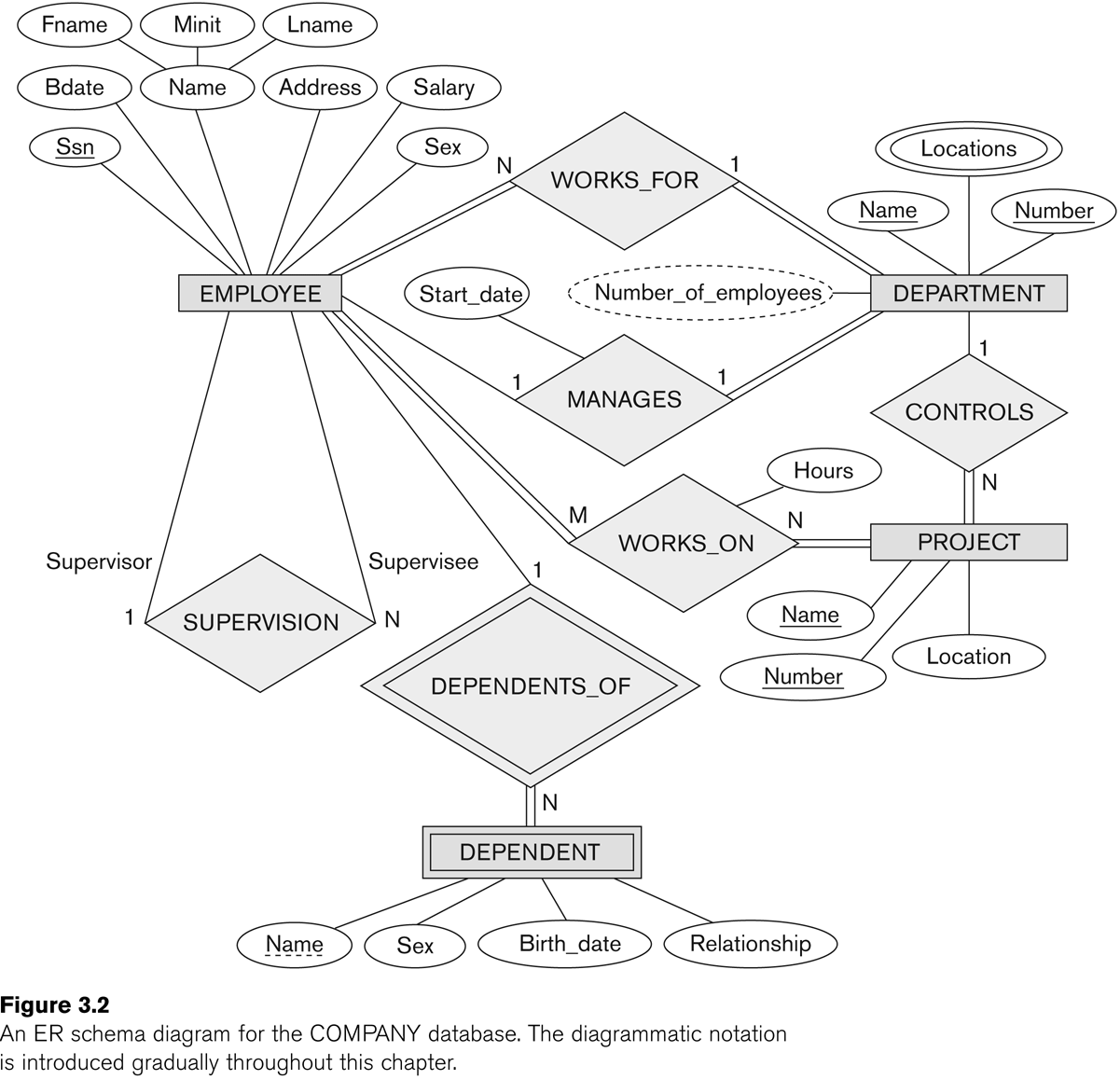
Now we should be able to go through Figure 7.2 (E&N p 204, below) in
detail. The relationships are supervises, works_for, manages, controls,
works_on, and dependents_of. Note that the name "supervision" is awkward; it
is not clear who is supervising whom. As a result, the entity links need
annotation with the role names "supervisor" and "supervisee". However, such
annotation is often a good idea for clarity.
(The figure below was Fig 3.2 in an earlier edition of E&N; it is Fig
7.2 in the 6th edition.)
Sometimes, as we rethink things, an attribute can be changed to a
relationship, or vice-versa. Sometimes an attribute may be promoted to an
entity, particularly if it was used in several other entities, in which case
we may also add a relationship to
those other entities.
Relationship attributes can sometimes be moved to entities. For a 1:1
relationship, the relationship attribute can be moved to either entity. For
a 1:N relationship, the relationship attribute can only be moved to the N
side. Consider the earlier examples:
DEPARTMENT ----1--- employs ----N-----
EMPLOYEE attribute: start_date, etc
EMPLOYEE -----1----- supervises ----N------EMPLOYEE
attribute: review_date
DEPARTMENT ----1----
controls-----N------PROJECT attribute:
project_budget_num
Sometimes we have entity attributes that need to be translated into
relationships. See Section 7.6. We would move manager information from the
DEPARTMENT entity to the MANAGES relationship. We started out with manager
as an attribute of departments, but later realized that there was a
relationship involved because two
entities were involved: DEPARTMENT and EMPLOYEE. This suggests the need for
a relationship.
We would move controlling-department information from the PROJECT entity to
the CONTROLS relationship. We would remove department, supervisor, and
works_on from EMPLOYEE. Note that some of these will eventually be added
back. At this point, we should have eliminated most multi-valued attributes.
ER diagram for the STUDENT database
Entities:
- student (name, student_number,
class, major)
- course (course_name, course_number, credit_hours, department)
- section (section_identifier, semester, year,
instructor) // why not
course_number?
Relationships:
course----< PREREQUISITE >---- course
section----< IS_OFFERING_OF >---- course
student ----< REGISTERS_FOR >---- section
(min,max) annotation
Instead of labeling lines connecting a relationship to an entity with 1, M,
or N, we can also use a (min,max) notation, meaning that each entity e in
the entity set E must participate in at least min entries of the
relationship, and at most max. If min>0, the participation is total;
min=0 means partial participation. The max is denoted N when we mean it is
allowed to be >1.
Note that a 1-N relationship would have the values reversed using the
(min,max) notation:
DEPARTMENT ===1=== employs ===N===
EMPLOYEE // 1 dept
= N employees
DEPARTMENT -----(1,N)---- employs --- (1,1)-----
EMPLOYEE // dept can have 1..N employees
The second line, above, means that a given department can appear multiple
times in the EMPLOYS relationship; ie a department can have multiple
employees. An employee can appear only once; that is, can work for only a
single department. Every employee must appear at least once, and every
department.
(Recall that the parallel lines === in the first line above represent total
participation: every department has an employee, and every employee works
for some department. This is represented in the second line with the 1 as
the first coordinate of each pair.)
Full example of (min,max) annotation: Fig 7.15
Why do they say
department ----(4,N)---employs
----(1,1)----employee
?
Manages relationship: put into entity on (1,1) side rather than entity on
(0,1) side
(0,1) doesn't say anything about how often the participation can be 0.
Consider
MANAGES------- (0,1)-----manager
(employee)
SUPERVISION --- (0,1)--- supervisee (employee)
Most employees are not managers.
Almost all employees are supervised.
UML diagrams
See Figure 7.16. UML diagrams have space
for operations,which in the world
of databases we're not much concerned about. The big boxes are for entities;
relationships have been reduced to boxes that annotate links. A (min,max)
notation is used, but the label goes on the opposite
entity.
UML relationships (actually, ER relationships as well) may either be of association or of aggregation.
The latter implies a collection, eg of employees into one department.
How do we translate this to tables?
We'll get to this next, but note that a 1:1 relationship can be represented
as an attribute of either entity. A
1:N relationship can be modeled as an attribute of one
of the entities (the entity on the side of the N). M:N relationships must
get their own table.
ER-to-relational mapping
How do we build a database schema from an ER diagram?
Step 1: regular entities
We define a table for each non-weak entity. We use all the leaf attributes;
composite attributes are represented by their ungrouped components. Keys are
also declared. Attributes that were earlier pushed into relationships are
not yet included.
Step 2: weak entities
We create a table for each weak entity, adding the keys for the owner entity
type (or types) (this would mean employee ssn), and adding a foreign
key constraint to the owner-entity table.
We are likely to use the CASCADE option for drop/updates: if an employee ssn
is updated, then the dependent essn must be updated, and if an employee is
deleted, then all the dependents are deleted too.
Step 3: binary 1:1 relationships
Let S and T be the participating entities to 1:1 relationship R. We pick one
of the two -- say S -- and add to S a column that represents the primary key
of T, and all the attributes of R.
It is better to choose as S the entity that has total (or at least closer to
total) participation in R. For example, the manages relationship between
departments and employees is 1:1, but is total only for DEPARTMENT, and is
nowhere near total for EMPLOYEE. Thus, we add a column manager
to DEPARTMENT. However, adding a column manages
to EMPLOYEE would work.
We also add a foreign key constraint to S, on the new attribute, referring
to the primary key of T.
One alternative is to merge S and T into a single relationship; this makes
sense only if both have total
participation in R. This means that S and T each have the same number of
records, and each record s in S corresponds to exactly one t in T.
A third alternative is to set up a table R containing ⟨sk,tk⟩ key pairs.
Step 4: binary 1:N relationships
Let us suppose S---N---R---1---T. We now add T's key to S as an attribute
with foreign-key constraint. We must
add T's key to S; we cannot do it the other way around. In the relationship
DEPARTMENT ----1--- employs ----N----- EMPLOYEE
we would have S be EMPLOYEE; we would put a dno
column in EMPLOYEE (why can't we add an essn column to DEPARTMENT?)
An alternative is the <sk,tk> keypair table. This might be more
efficient if only a few s in S participate in the relationship; otherwise we
would have many NULLs in the T-column of S.
Step 5: binary M:N relationships
Here we must create a table R of tuples including the key of S (sk), the key
of T (tk), and any attributes of R; we can not
push the data into either S or T. Call the new table also R (note that
E&N call it S). The sk column of R should have a foreign key constraint
referring to the key column of S, and the tk column of R should similarly
have a foreign key constraint to the key column of T.
The WORKS_ON table is a canonical example; so is the GRADE_REPORT table.
Again we would likely to use the CASCADE option for deletion or update of
records in the participating entities S and T.
Step 6: multivalued attributes
If we have any left, they must be moved into their own tables. For example,
if employees can have several qualifications
(eg degrees or certifications), we would create a table QUALIFICATION with
two columns: essn and qualification. The DEPT_LOCATIONS table is similar.
Again, we would have an appropriate foreign key constraint back to the
original table.
Step 7: higher-degree relationships
These are handled like binary M:N relationships.
More on Foreign Keys
Here's the seven-step ER-to-relation algorithm again, slightly simplified:
- create a table for each regular entity
- create a table for each weak entity, adding the key field from the
owner entity as a foreign key for the new entity.
- for binary relationships between entities E1 and E2, pick one of them
(eg E1) and add to it a field conntaining the key to E2. Make this a
foreign key in E1.
- for binary 1:N relationships between E1 and E2, E1---1---R---N---E2,
add a column to E2 containing the key of E1. Make this a foreign key in
E2.
- For binary N:M relationships between E1 and E2, create a new table R
consisting of ⟨E1.key, E2.key, R.attributes⟩. Make E1.key and E2.key
foreign keys in R.
- For multivalued attributes of entity E, create a new relation R. One
column of R will be E.key; this should be a foreign key in R.
- ternary and higher-degree relationships: like step 5.
Joins arise in steps 2, 3, 4, 5, 6,
and 7, for recovering the original
relationships (or attribute sets for 6, or entities for 2). In
every case, the join field is a key of one relation and a foreign
key in the other.
Not all joins are about recovering
relations from an ER diagram.
Also, I said earlier that entity T should not have an attribute that was
another entity of type S; instead, we should create a relationship R between
T and S. If S was at all a candidate for an attribute,
each T would be related to at most one S and so this would have cardinality
constraint T---N---R---1---S. Then, when we did the above conversion, in
step four we would add S's key to T with a foreign key constraint referring
to S.
But suppose we did add S as an
entity attribute to T. Then we would end up with the same situation: we
would use the key of S as an
attribute of T, and create the same foreign-key constraint. So in the end we
get the same thing.
Invoice
How shall we model invoices? An invoice is a collection of parts ordered,
each with a quantity. One way is to try to model an invoice (or at least an
invoice_item) as a binary relationship between CUSTOMER and PART, with
attributes date and quantity. An invoice is thus all the items to the same
customer with the same date.
CUSTOMER---<INVOICE_ITEM>---PART
|
date
|
quantity
An invoice would be uniquely determined by the date, so if Customer c
ordered part P on date D with quantity q we would have ⟨c,p,d,q⟩ ∈ Invoice.
Given ⟨c,d⟩ we can look up all the parts p and, for each part, the quantity.
For a given c and d there might be multiple parts p that were part of the
invoice. We can search the Invoice table for those ⟨c,d⟩, and find the
balance of each record.
Problem: INVOICE is not actually a
"relationship set" for entities Customer and Part, as defined in E&N
§7.4.1; a relationship would have to be a subset of the cross product
Customer × Part; we can add attributes, but
the ⟨c,p⟩ part is supposed to determine the record. However, the
values of c and p do not determine
an INVOICE record. The key for INVOICE is the triple
⟨c,p,d⟩; a customer c can order 100 units of d on 2005-12-01 and then 200
more units on 2006-01-27.
What we really have here is that INVOICE is a ternary
relationship between Customer, Part, and a single-attribute entity
Order_Date. Ternary relationships tend to be inefficient. None of the
relationships in the COMPANY database were ternary; in WORKS_ON, a record
was uniquely determined by the essn and the project_num; in WORKS_FOR, by
the ssn and the dept_no.
A much more common approach (which also allows multiple invoices on a single
day) is to use a synthetic key invoice_num
to create an entity Invoice. This
is an instance of a rather general strategy that might be called the synthetic-key trick: convert a
relationship to an entity by assigning a "serial number" to each tuple in
the relationship. In this case the synthetic key has a natural
interpretation: we number each order as it is placed. For the works_on
relationship of the COMPANY database we might use a synthetic key called
Job_Assignment_Num; for the Works_For relationship between Employees and
Departments we might use Job_Association_Num.
Once we make Invoice an entity, we identify its attributes Cust_id and
Order_date. We also have a new relationship Invoice_Item (it could also be
called Part_of_Order), as follows:
Invoice ---------
Invoice_Item ---------- Part
|
quantity
(Actually, Invoice also has a relationship Ordered_By to Customer; that is
N:1 so I have immediately implemented it by adding a Cust_id attribute to
Invoice. We replaced one sort-of-binary relationship Invoice between
Customer and Part with a new entity
Invoice with binary relationships to each of Customer and Part. But only the
relationship with Part is M:N and so needs it own table.)
We implement Invoice_Item as its own table listing invoice numbers, part
numbers and quantities. The primary key is the pair ⟨invoice_num, part_num⟩;
the table also has an attribute for quantity (and perhaps also for
current_price, or for discount). The INVOICE table might look like this:
Table Invoice
Invoice_num
|
Cust_id
|
Order_date
|
10001
|
201
|
2011-11-17
|
10002
|
251
|
2011-11-17
|
10003
|
201
|
2011-11-25
|
10004
|
287
|
2011-11-25
|
and the table Invoice_Items might look like this:
Table Invoice_Item
Invoice_num
|
Part_num
|
Quantity
|
10001
|
37
|
50
|
10001
|
41
|
100
|
10002
|
83
|
4
|
10003
|
37
|
200
|
10003
|
59
|
100
|
10004
|
37
|
100
|
Bottom line:
- The original INVOICE relationship
turned out to be ternary rather than binary
- When we made INVOICE an entity,
by using the synthetic-key trick,
we just had one strictly-binary table to implement
ER-to-relation mapping of ternary and other higher-degree relationships
Consider the SUPPLY relationship on a supplier s, project j, and part p. The
tuple ⟨s,j,p⟩ is included if supplier s supplies part p for project j.
We might try to model this with three binary relationships, SUPPLIES(s,j),
CAN_SUPPLY(s,p), and USES(j,p). It is true that if ⟨s,j,p⟩ is in SUPPLY,
then ⟨s,j⟩ is in SUPPLIES, ⟨s,p⟩ is in CAN_SUPPLY, and ⟨j,p⟩ is in USES. But
the converse is not true (example). If we build the three binary tables, we
cannot reconstruct the ternary table.
See Fig 7.17.
As for binary relationships, a ternary relationship key is a triple of keys
from each participating entity.
Ternary relationships can be problematic, and so we often include
corresponding binary relationships, sometimes even if they are reundant.
One approach is to model a ternary relationship as a weak entity, with three
identifying relationships (Fig 7.17(c)).
This is usually done only when the underlying ER-modeling tools do not
support ternary relationships. The resultant entity has the requisite
three-attribute key to describe the ternary relationship accurately.
Alternatively, we can give SUPPLY a synthetic ("surrogate") key,
supply_id, and then relate it to SUPPLIER, PROJECT, AND PART by binary
relationships. The synthetic key would uniquely determine a ⟨s,j,p⟩ triple;
we can say this in SQL by saying that ⟨s,j,p⟩ is a secondary key. With a
synthetic key we now have an entity
SUPPLY, with key supply_id si, and with three relationships SUPPLIES3(si, s,
j), CAN_SUPPLY3(si,s,p) and USES3(si,j,p). We may still need a ternary
relationship explaining the relationship of all three, but from the entity
SUPPLY(supply_id, supplier, project,
part) we can now reconstruct the original ternary table.
The next example is OFFERS, for a school database; see Fig
7.18; ⟨i,s,c⟩ belongs to OFFERS if INSTRUCTOR i teaches COURSE c
during SEMESTER s. Again, the binary projections fail to adequately model
the ternary relationship. E&N suggest that if one of the binary
relationships is 1:1 (eg if the CAN_TEACH(i,c) relationship is 1:1), then
this does work, but that is seldom if ever the case.
Actually, in a real school database one would not use OFFERS, one would use
SECTION. The latter would likely be an entity, complete with synthetic key
section_id. However, SECTIONs are determined by instructor i, course c,
semester s, and timeslot ts, or, alternatively, by semester and course and
section_number or semester and class
number (Loyola's mechanism).
Ternary relationships can have cardinality tags, like binary relationships,
but they are not as straightforward. For the SUPPLY relationship, suppose
each project,part pair (j,p) can have only one supplier. Then we might put a
1 on the SUPPLIER link. But it might also be the case that each project j
uses a unique supplier,part pair (s,p) (that is, each supplier can supply
only one part to each project). We now have an unrelated
1 on the PROJECT link.
The (min,max) relationship is more straightforward: E------(m,M)-----R means
that for each e in E, there are at least m tuples involving e in R, and at
most M. But this method cannot describe the case where each project/part
combination can have only one supplier.
Translation from higher-degree relationships to SQL table definitions is
done the same way as for binary M:N relationships: we create a table
consisting of columns for keys for each of the participating entities, and
any relationship attributes. The entity keys form the primary key for the
new table, and each entity key has a foreign key constraint referring back
to its defining entity table.
A look at PHP PDO and LAMP (or WAMP)
See also EN16 chapter 14, but notice that there they use the PEAR library.
This can be tricky to install under windows, so I've converted to the
simpler PDO library. The differences are minor, and Chapter 14 is still a
very useful reference, but be aware.
What I had to do:
install php5
install php5-mysql
install the php.ini-development file (to enable error
messages)
If error messages are not enabled, you are doomed.
phpinfo.php
pdo_demos.php
lib353pdo.php
employee.php
For the employee.php file, note the following:
- connect_pdo()
- examining $_POST for keys submit, update, deralph, none-of-the-above
- printform()
- department menus
- look at html form code
Try removing the ";" from the include
statement in pdo_demos.php to admire the elegance and precision of the
resultant error message:
Parse error:
syntax error, unexpected '$hostname' (T_VARIABLE) in /var/www/company/pdo_demos.php
on line 7
(Can you figure out why it is complaining about line 7 for an error that is
actually on line 3?)