SIP, SDP and Friends

Peter Dordal, Loyola University CS Department


In this section we look at the Session Initiation Protocol, SIP, and other IP-based protocols (primarily) for VoIP.

SIP/SDP & H.323

These are all forms of session-setup protocols; the actual data transfer would then be handled via RTP or the equivalent (below). SIP & SDP are IETF protocols; H.323 is standardized by the International Telecommunications Union. Within the TCP/IP world, this means that there tends to be a bias in favor of SIP. H.323 may provide more complete switching options, but nobody really cares; SIP provides everything you need to place calls and is more widely supported.

SIP

One of the deepest differences between SIP and SS7 is that SS7 is centralized and SIP is entirely between the endpoints. In SIP, there are no reserved channels because there are no channels to reserve: SIP messages and the voice data packets travel on the global internet.

Another is that we now have to negotiate the encoding used, eg µlaw (also known as G.711). SIP doesn't actually do this itself; it leaves that up to SDP. Strictly speaking, SS7 has to negotiate the encoding too, but the only choices are usually µlaw or Alaw.

Another difference is that while SIP very happily serves to connect voice-call endpoints (ie phone numbers), its endpoint-naming schema is in fact much more general. SIP can also be used for multi-endpoint teleconferencing. It can also be used for game setup, or for instant messaging.

SIP's message format is somewhat similar to HTTP. It is often used in conjunction with the Session Description Protocol (SDP); the SDP data defines the format of the proposed call and is typically encapsulated in the SIP packet. SDP allows specification of IP addresses, names, and specific formats for the data streams. SIP can interact with Signaling System 7, though the two are structurally rather different.

SIP can be used to get two Asterisk servers to communicate, though it is more common to use IAX for that.

Goals for SIP include:
Often the initial connection to a user is made to a SIP proxy; the asterisk server acts as a proxy for the Cisco phones. If your phones are behind a NAT firewall, you will need a proxy outside. Proxies forward SIP packets, perhaps after editing them; proxies may negotiate (or allow the endpoints to negotiate) a more direct route for the actual call path. Proxies typically know the locations of the various local telephones; there is a SIP registration mechanism for a phone to announce itself to, say, its Asterisk server. A proxy may also fork a call to multiple devices (eg to my desk phone and my cell phone); forking may either be parallel (ring both simultaneously) or sequential (ring one for 15 seconds, then the other).

In Asterisk, sequential ringing is done by one Dial() call followed by another; the first Dial() call must have a timeout. Parallel ringing is handled by including both channels in a single Dial() call.

SIP endpoints are User Agents, or UAs. Other entities are
Connections start with a sip URI (uniform resource identifier -- not locator!), eg
The part of a SIP URI to the right of the "@" represents a host to be contacted, that is, the "remote proxy" (it might not be the final remote proxy, however). The part to the left of the "@" is to be interpreted by the remote proxy. In some cases it represents a telephone number; in other cases, it represents some identifier that the remote proxy knows how to find and page.

The most common SIP messages are
SIP packet bodies contain ASCII text spelling out all the fields. This allows flexible addition of new fields; for example, SIP INVITEs from flowroute for inbound calls often contain the P-Asserted-Identity field (from SS7/ISUP).

Someone calling me would start with an INVITE message, sent by their proxy (the User Agent Client, or UAC) to mine. My proxy may not be the final stage, however. As the INVITE message is passed along, each proxy returns the message 100 Trying. Eventually the INVITE reaches the end of the path (or fails), and the phone rings. It also sends back 180 Ringing, and sometimes also 183 Session in Progress. When the phone is answered, it sends back 200 OK along the proxy chain. Sometimes there are SIP proxies ("stateless" proxies) that lie between proxyA and proxyB on the path, but which "edit themselves out" of the final signaling path.

One of the purposes of the proxies is to allow connection to sip:pld@cs.luc.edu through any of several phones, thus supporting forwarding: my office phone first, but my cell phone if I have pressed a button on my office phone to forward calls.

The actual data (the RTP packets) do not traverse the proxy path; they take the most direct route they can. Note, however, that endpoints behind NAT firewalls will need some kind of proxy.

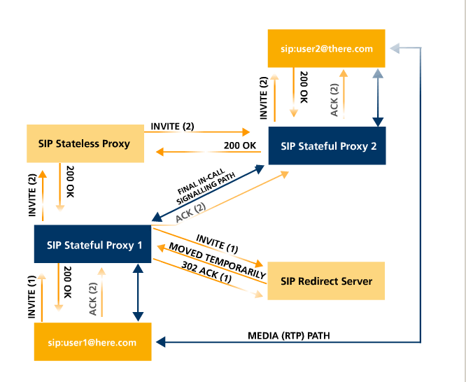
SIP connection setup with proxies

In the above picture (from http://en.wikipedia.org/wiki/File:SIP_signaling.png), the following has happened:
  1. user1 sent INVITE(1) to Proxy1
  2. Proxy1 sent INVITE(1) to the Redirect Server, which responds with MOVED TEMPORARILY
  3. Proxy1 then sent a new INVITE, INVITE(2), to the Stateless Proxy
  4. INVITE(2) is forwarded to Proxy2
  5. Proxy2 forwards it to user2
  6. User2 sends back 200 OK, which traverses Proxy 2, Stateless Proxy, and Proxy 1
  7. User1 then sends ACK(2), which bypasses the Stateless Proxy (no longer in the "path")

               proxy1------------proxy2
              /                        \
             /                          \
            /                            \
         user1------- media path -------user2


This arrangement is sometimes called the SIP trapezoid.

Note that, when flowroute.com (in California or Nevada) is proxy2, then user2 is likely to be a SIP-to-SS7 transfer point ideally in the LATA of the PSTN side of the call. That is, if I'm calling someone in Pennsylvania, proxy2 is in California but hopefully user2 is in Pennsylvania.

One important field in the SIP header is the Call-ID, which is a unique identifier for referring to this call in subsequent packets. In the To: field there is usually a "tag" field with another unique identifier. This tag can be chosen independently by each side, and may be chosen uniquely for each transaction (related set of packets). From RFC 3261:

Call-ID contains a globally unique identifier for this call, generated by the combination of a random string and the softphone's host name or IP address.  The combination of the To tag, From tag, and Call-ID completely defines a peer-to-peer SIP relationship between Alice and Bob and is referred to as a dialog.

UDP v TCP

SIP can run on UDP or TCP. For most VoIP applications, UDP is the transport layer of choice. Just why this is so, however, is not as clear as it might be. The actual RTP data, of course, needs to use UDP so that a lost data packet can be ignored. TCP forces a wait until any lost packet is retransmitted. Would the delay for a lost INVITE packet be unacceptable? SIP over UDP has to have its own timeout mechanisms.

One advantage of having SIP use UDP, aside from the real-time aspect, is that the transition from including the proxies in the communication path to omitting them can be made seamlessly. At any point, either endpoint can start sending to another entity (eg the other proxy or the other endpoint).

Note that in the diagram above, the INVITE, 200 OK and ACK(2) packets form a three-way handshake.

When SIP is sent over UDP, the following simple timeout/retransmission mechanism is used [RFC 3261]

the client transaction retransmits requests at an interval that starts at T1 seconds and doubles after every retransmission.  T1 is an estimate of the round-trip time (RTT), and it defaults to 500 ms.

ACKS are, as with TCP, not themselves acknowledged.

Traversing NAT

This is actually somewhat easier for TCP, at least in terms of having a phone behind a NAT firewall register itself to an Asterisk server. However, the problem then becomes what to do when the proxies drop out (in some cases, the proxies simply cannot drop out).

    proxy ------------------------ NAT firewall --------------------- phone

SIP usually uses port 5060. Generally, if there is only one device behind a NAT firewall trying to reach a proxy on the outside, and it uses source port 5060, then port 5060 will be passed through unchanged. That is, packets will arrive at the proxy from port 5060 of the NAT firewall; the source port number will not  be remapped. (However, if there are two hosts inside trying to reach the outside from port 5059, one would be remapped, possibly to 5060, leading to a need to remap the phone's use of port 5060). Alternatively, some NAT firewalls allow punching through certain "holes" for designated ⟨host,port⟩ combinations on the inside.

Finally, it is possible that the packets from the inside phone will be remapped. The packets will arrive at the outside proxy's port 5060, but appear to be coming from another port on the NAT firewall, perhaps 5067. In this case, as long as the proxy remembers this source port, it can always reply.

SIP registration packets are sent at periodic intervals; one consequence of this is that the firewall is kept "open". At any time, the proxy can reply to the phone by sending to the firewall with the port that the phone appears outside the firewall to be using as its source port.

When the SIP end users leave the proxies out of the path and begin direct communication, they get each other's IP address from the SIP packets so far. That IP address will be wrong if one endpoint is behind a NAT firewall. Furthermore, if the other phone tries to send to the phone shown above through the NAT firewall, the firewall will not be open for packets coming from other-phone's IP address. The bottom line is that if one phone/user is behind a NAT firewall, its proxy probably cannot drop out of the media path.

In asterisk, the media path is initially set up through the asterisk proxy. The asterisk proxy can then issue a SIP RE-INVITE request to modify this to allow direct communication between the endpoints. The "reinvite=no" option disables this, and thus is generally required when an endpoint is behind a NAT firewall.


SIP Registration

When you first set up a SIP phone, it needs to register with your proxy (eg your VoIP provider or Asterisk box). This is roughly equivalent by having the phone "log in" to the registry server (which can be different from your actual SIP proxy).

The cisco phone uses the information in the Subscriber Information section (admin/advanced/Ext1). Normally registration is based on the userid (eg cisco55311eline1) and the password. Compare that information with what is in ulam2's sip.conf file.

When the phone registers, one (no longer supported) option is for it to send its ID and password; this is known as the SIP "basic authentication" protocol. But it is now officially forbidden, as it exposes the password to eavesdroppers. The SPA (cisphone) does not use basic authentication; instead it attempts to use digest authentication. In registration.pcap, I did a packet trace just after rebooting the phone (forcing it to re-register). In packet 1 the cisphone sends a request containing
The response is an MD5 hash of the username, password, nonce, and URI. A "nonce" is a short-term string used in the challenge-response protocol; it is generated by the asterisk server and likely encodes a private per-server key, the identity of the remote phone (cisphone), and a timestamp. Because the password is included in the string hashed to create the response, presumably only an endpoint in possession of the password could have created the response. The phone server can verify the response because it too knows the password, and everything else is public.

The purpose of including the nonce is to prevent replay attacks; after the registration has expired (typically after 3600 seconds), a given response string can no longer be used.

The reply to the above registration attempt is packet 2, 401 Unauthorized; registration fails because the cisphone was using an old nonce value. The reply packet also includes a new nonce word of "5c4841da". The other lines of the cisphone also try to register with the old nonce, and fail; the phone is  a four-line phone and each line can register independently of the others. Often I have some of the other lines register with other SIP servers.

In packet 9, the cisphone tries again to register, this time using the new nonce. The new response computed by the cisphone is "f7372e4bd340c82ea0a275d9a6ec76a7". The server reply indicating success is packet 11.

It is also possible to register multiple phones with the same username. In this case, all ring when a call comes in. This is a simple way of setting up a "call group", but is generally intended when all phones represent the "same" user. (Another application of call groups is having calls to the sales number ring the phones of every salesperson.)

Finally, there is a certificate option for registration authentication, which uses public-key encryption. As long as there is not a problem provisioning the phone and server with the same password string, however, public-key authentication is not needed and provides no additional security.


H.323

This is rather like SIP, except everything has a different name. (To be fair, there are also additional features). Proxy servers are known as Gatekeepers or Peer Elements or Border Elements. H.323 has more features for admission control and authentication. Where SIP connections begin with an INVITE message, H.323 may (this is what the telecom world is like) begin with a Request for Permission To Call.

See http://en.wikipedia.org/wiki/H.323.

One advantage of SIP, as a protocol, is its greater flexibility. New data formats can be added to SDP very quickly; getting revisions to H.323 usually takes years and can take decades.


SDP

The Session Description Protocol has to negotiate the connection. At the SIP level, this could be point-to-point audio, multicast audio, video, or even something else.

For VoIP purposes, the main role of SDP is to negotiate the codec, or voice-data-encoding algorithm, used by the connection, and also the media path. Here are some options, from the O'Reilly  Asterisk-The Definitive Guide book, Appendix B: Protocols for VoIP:

Codec Data bitrate (Kbps) License required?
G.711 64 Kbps No
G.726 16, 24, 32, or 40 Kbps No
G.729A 8 Kbps Yes (no for pass-through)
GSM 13 Kbps No
iLBC 13.3 Kbps (30-ms frames) or 15.2 Kbps (20-ms frames) No
Speex Variable (between 2.15 and 22.4 Kbps) No
G.722 64 Kbps No

G.711 is, of course, µlaw. There is no compression beyond companding.

G.729 is a remarkably efficient form of compression, though it is CPU-intensive. The latter matters only if you're doing the compression/decompression on a shared switch; if your phone can do G.729 itself then this is not an issue.

The compression algorithms used by G.729A are tuned to voice; so much so, in fact, that DTMF (touch-tone) tones are not properly carried! The process starts with a 10 ms block of 16-bit samples (80 samples). The patented algorithm is known as Algebraic Code-Excited Linear Prediction (ACELP). Each block is run through two digital filters, one to create an average pitch for the block and one called the "stochastic" contribution. The latter is encoded as an entry in a large "codebook" that is built into the algorithm. The codebook (and the average-pitch phase) attempts to use a model of how human-speech sounds are produced.

Speex also uses generic CELP.

Demo of G.729


VoIP and Jitter Buffer

VoIP calls have to deal with a much larger round-trip time than PSTN calls, easily 100-200 ms versus the PSTN's delay of 1-2 ms on a DS-0 line.

However, the delay is often chosen to be larger than the initially measured RTT. This is to have a hedge against increases in the RTT; the "voice RTT" should be larger than the worst-case "packet RTT".

Diagram?

Sometimes, if we realize the voice-RTT estimate was chosen too large, we can reduce it, either by paring away a few voice samples at a time, or by reducing times when the line is silent (we need some form of "silence detection" for this).


RTP & RTCP

RTP is Realtime Transport Protocol, a generic UDP-based way of sending "realtime" (audio and video) data. The RTP header contains:
Examples of CSRCs might be synchronized video feeds from multiple locations or cameras, or synchronized feeds from multiple microphones. Synchronized audio and video is also possible, but deprecated; the preferred strategy is to send audio and video as two separate flows. That way, if one wants to renegotiate the encoding, it is free to do so.

RTP does not use a designated port. (Nor is there an evident "signature" for RTP packets, making them sometimes hard to identify in packet traces). In the SIP/SDH packets immediately before the RTP exchange, the port(s) to be used by the RTP packets are identified.

In the Asterisk rtp.conf file, I specified the RTP port range as 19000-20000. These are the local ports used by ulam2; the other end of course chooses its local port.

In my wireshark file g729.outbound.frontier.pcap (ie to Frontier Telecommunications, my home landline provider), I placed a call from a cisphone directly connected to ulam2 via a private network tunnel. Ulam2 chooses port 19522 and the remote RTP end, 67.16.104.172 (an IP address reasonably near my home), chooses port 50836. Ulam2 specifieds this port 19522 in both SIP/SDP packets it sends (1 and 5). Packet 7 is the one SIP/SDH packet from flowroute (216.115.69.144), and the SDH body identifies its RTP host (67.16.104.172, in "Connection Information => Connection Address") and port (50836, in "Media Description => Media Port"; Media Format of G.729 is also identified here). The very next packet (the first RTP packet) is sent by ulam2 to 67.16.104.172 / 50836.

Note that ulam2 does not specify a different host; that is, there is no "reinvite" at its end. That's because I told it not to ("reinvite=no"), which in turn is because the actual phone is behind a NAT firewall; ulam2 continues to forward RTP packets between the cisphone and 67.16.104.172. IP addresses and ports embedded in the communications stream are particularly difficult for NAT firewalls to handle, as the behind-NAT sender's idea of what its IP address and port are will have almost no relation to the actual IP address and port. (For SIP, we might actually get the same port, 5060, as long as we're the first to ask for it.) It is actually the SDP packets, carried within SIP packets, that hold the media-stream contact information. In Asterisk, the sip.conf option "nat=yes" causes any new IP address or port in the SDP packets to be ignored; the media stream is sent to the same host as the SIP packets.

In my wireshark file g729.outbound.loyola.pcap, I called my Loyola office phone from my office cisphone, which reaches ulam2 through a NAT firewall (10.38.2.42). I traced not only the RTP packets between ulam2 and the other end, but also the RTP packets to the cisphone. We see the following:

packet 1: SIP/SDP INVITE from firewall to ulam2, containing a Connection Address of 10.213.119.31. This is a behind-the-NAT address; ulam2 can not reach it. There is also a port specified (16472), and multiple media formats (G.729, G.711, G.721, G.722, ....).

packet 4: Pretty much the same, after some authentication

packet 6: SIP INVITE from ulam2 to sip.flowroute.com (216.115.69.144), specifying Connection Address = ulam2 (ie not 10.213.119.31 or 10.38.2.42), and port 19116; G.729 is the only codec offered

packet 10: Again, pretty much the same, but after authentication

packets 13-15: These look like early RTP packets from the far end. At this point ulam2 has no idea who they are from!

packet 16: This is the first SIP/SDP packet from sip.flowroute.com to ulam2, identifying the remote end as 68.68.120.43 / 9998, identified by ip2location.com as being in Morgantown, WV.

packet 17: SIP/SDP from ulam2 to the firewall, specifying the connection as 147.126.65.47 / 19098; that is, ulam2 again.
The rest is the RTP stream, including both the local stream between ulam2 and the cisphone/firewall and the longhaul stream from ulam2 to West Virginia.
Note packets 19, 21, 23 and 25, which ulam2 attempted to send directly to the cisphone at hidden address 10.213.119.31. They never got there. After that, we see each packet twice, once between ulam2 and 68.68.120.43 and once between ulam2 and 10.38.2.42. The packets to 10.213.119.31 stop as soon as the first RTP packet from the cisphone, via the firewall, arrives at ulam2 as packet 26. At this point ulam2 recognizes the packet as part of the RTP flow it is expecting from cisphone, and uses the packet's source address (the firewall) as the address to send future RTP packets to, rather than the IP address of 10.213.119.31 announced in packets 1 and 4.

To summarize: the SIP protocol as such uses port 5060, and gets through a firewall by
RTP  relies either on (a) not trying to get through NAT firewalls at all, or noticing that the real address/port from which RTP packets are arriving from behind the firewall is not the "advertised" address/port, and using the real address/port instead. There is also a manual configuration option for NAT exceptions, and there are also "NAT-traversal" protocols such as SOCKS or NAT-T that allow certain ports behind a NAT firewall to be "opened up".

The switch to this new IP address / port is in Asterisk called a "reinvite"; the SIP protocol uses this term for modifications of an existing negotiated media stream.

With cisphone behind a NAT firewall, ulam2 can reach it by replying back. What if ulam2 itself were behind a firewall? Then it would REGISTER itself to sip.flowroute.com and continue sending keepalives to sip.flowroute.com to stay in touch. Then flowroute could reply to ulam2, at least to port 5060. There is a mechanism for manual configuration (and again keepalives) of a handful of ports for the RTP traffic, but I'm not very familiar with it.


We earlier looked at some of the RTP packets from a call placed by the cisco VoIP phone using G.711. These packets were 214 bytes, consisting of
Because the RTP header was only 12 bytes, there were no CSRCs, which is what we would expect for a single voice channel. The RTP payload type was 0x00, which is desigated as ITU-T G.711 PCMU, which is µ-law/A-law logarithmic companding of 8-bit PCM audio with a sampling rate of 8000.

Other payload-type codes may be found in RFC 3551, page 33 (RTP A/V Profile).

Compare the RTP packets for a G.729 connection. The packets still have the 14-byte Ethernet header, 20-byte IP header, 8-byte UDP header and 12-byte RTP header. However, the data for 20 ms now takes only 20 bytes, for a total packet size of 74. Note that, for these packets, these headers now take up 73% of the total!

RTP timestamps are provided by the sending application, and are application-specific. Their primary purpose is to synchronize playback. For the cisco phone, the timestamps were in multiples of 160, starting at 160; these would represent the number of "sampling ticks" (at the rate of 8000/sec) up to the end of the current data.

RTP packets are generated only by the sender; the flow is one-way. The RTP protocol does not include any form of acknowledgement. However, associated with RTP is the Realtime Transport Control Protocol (sometimes called RTP Control Protocol), or RTCP. This has several goals, in each direction; one goal is to support tagging of RTP streams, and to support coordination and mixing of RTP streams that have not been mixed at the SSRC/CSRC level. However, for our purposes the primary goal of RTCP is to provide acknowledgment-like feedback from receiver to sender, indicating the packet loss rate. Here is that portion of the data from one of the cisco RTCP Receiver Report (RR) packets (packet 3013) from g729.outbound.loyola.pcap (Real-time Transport Control Protocol (Receiver Report) → Stream setup by SDP → Source 1 → SSRC contents):
RTCP packets are not sent often; in the g729.outbound.loyola.pcap file there is a pair at positions 1006 and 1007, a pair at 2010/2011 and the final pair at 3012/3013.

RTP applications can elect to receive this information (in particular, the fraction lost), and adjust their sending rates (eg by choosing a different encoding) appropriately. But if the RTCP reports are unsatisfactory, and the RTP data stream cannot adapt to a lower bandwidth, there is not much point bothering to receive the report. The jitter portion of the RTCP message is always potentially usable, because if jitter is higher than it was any RTP receiver can adapt simply by increasing the size of its playback buffer (that is, increasing the delay between average arrival time and actual playback). But the jitter is seldom an important issue.

In fact, when the cisphone is using µlaw encoding, it does not seem to send RTCP packets under any circumstances! A possible reason for this is that there is no possibility of making use of the data within them; g.711 is completely nonadaptive. (g.729a is also nonadaptive, in practice, but the phone seems to send the reports anyway.)

Also, when the asterisk server remains in the path, it too does not initiate any RTCP packets. In this case, however, that is because it is not an endpoint to the exchange.

There is a Java interface to RTP, java.net.rtp (not part of the standard Oracle/Sun library). In this package, an application that wishes to receive RTCP information can create an RTCP_actionListener, which is invoked asynchronously whenever RTCP packets arrive, much like a mouse Listener. A standard GUI interface, however, may consist of essentially nothing but various asynchronous Listeners. A typical RTP program, on the other hand, will have at least one main thread involved in the transfer of data, and which will receive some form of messages or notification (perhaps by setting shared variables) from the RTCP_actionListener.

If you watch a movie on Netflix or Hulu, the video encoding is highly adaptive: if bandwidth is reduced, the video encoder is changed to a lower rate. Originally, Netflix transmitted at one of 2200 kbps, 1600 kbps, 1000 kbps and 500 kbps (with progressively poorer resolution as the rate decreased); your rate might change mid-session as less (or more) bandwidth was available.

I doubt Netflix uses RTP, but, if it did, then it is the returning RTCP packets that provide input to the video transmitter at the Netflix end as to what encoding rate to use.

If, as is more likely, Netflix uses TCP to send the video data, then it is the rate of returning conventional ACKs that determines the effective bandwidth. This can be measured from "userland" (non-kernel land) at the sending side by recording the time for every send()/write() operation; after some startup buffering, these operations block until the TCP window is able to transmit more data. Another strategy is to use user-level acknowledgments; that is, to have the transport channel receiving end send back regular reports. In the file ouat2.pcap, the video seems to be from 8.27.82.254; we can focus on these packets with tcp and ip.host == 8.27.82.254. Some of the acknowledgements also contain data. In addition, there are various RTMP (Real Time Messaging Protocol) packets; this is a semi-proprietary Macromedia protocol used for supporting flash video.

Netflix has now [2012?] licensed the eyeIO technology for variable-rate video encoding.

I have some packet traces of watching something on hulu.com; hulu most definitely does not use RTP.