Comp 346/488: Intro to Telecommunications

Tuesdays 4:15-6:45, Lewis Towers 412

Class 10, Mar 27

Reading (7th -- 9th editions)


Topics:


G.729a voice encoding and CELP (Code-Excited Linear Prediction)

CELP and other advanced speech-compression algorithms proceed as follows (see http://www-mobile.ecs.soton.ac.uk/speech_codecs/hybrid.html)
  1. For each block of speech, subtract the pitch component
  2. Apply "predictors" to address the expectations of pulse distribution in the remainder
  3. Run the remainder through every entry in the codebook to find the one that gives the closest match to the original
When CELP was developed in the 1980s, apparently it took 125 sec of Cray supercomputer time to process each 1 second of actual voice. The algorithm has improved considerably since then.


RTP & RTCP

In my wireshark file g729.outbound.loyola.pcap, I called my Loyola office phone from my office cisphone, which reaches ulam2 through a NAT firewall (10.38.2.42). I traced not only the RTP packets between ulam2 and the other end, but also the RTP packets to the cisphone. We looked at the following:

packet 1 & 4: SIP/SDP INVITE from firewall to ulam2, containing a Connection Address of 10.213.119.31. This is a behind-the-NAT address; ulam2 can not reach it. There is also a port specified (16472), and multiple media formats (G.729, G.711, G.721, G.722, ....).

packet 6 & 10: SIP INVITE from ulam2 to sip.flowroute.com (216.115.69.144), specifying Connection Address = ulam2 (ie not 10.213.119.31 or 10.38.2.42), and port 19116; G.729 is the only codec offered

packets 13-15: These look like early RTP packets from the far end. At this point ulam2 has no idea who they are from, as flowroute has not yet notified ulam2.

packet 16: This is the first SIP/SDP packet from sip.flowroute.com to ulam2, identifying the remote end as 68.68.120.43 / 9998, identified by ip2location.com as being in Morgantown, WV.

packet 17: SIP/SDP from ulam2 to the firewall, specifying the connection as 147.126.65.47 / 19098; that is, ulam2 again.
The rest is the RTP stream, including both the local stream between ulam2 and the cisphone/firewall and the longhaul stream from ulam2 to West Virginia.
Note packets 19, 21, 23 and 25, which ulam2 attempted to send directly to the cisphone at hidden address 10.213.119.31. They never got there. After that, we see each packet twice, once between ulam2 and 68.68.120.43 and once between ulam2 and 10.38.2.42. The packets to 10.213.119.31 stop as soon as the first RTP packet from the cisphone, via the firewall, arrives at ulam2 as packet 26. At this point ulam2 recognizes the packet as part of the RTP flow it is expecting from cisphone, and uses the packet's source address (the firewall) as the address to send future RTP packets to, rather than the IP address of 10.213.119.31 announced in packets 1 and 4. This represents a common NAT strategy of replying back to the source address rather than to the address claimed in the packet.


RTP packets are generated only by the sender; the flow is one-way. The RTP protocol does not include any form of acknowledgement. However, associated with RTP is the Realtime Transport Control Protocol (sometimes called RTP Control Protocol), or RTCP. This has several goals, in each direction; one goal is to support tagging of RTP streams, and to support coordination and mixing of RTP streams that have not been mixed ath the SSRC/CSRC level. However, for our purposes the primary goal of RTCP is to provide acknowledgment-like feedback from receiver to sender, indicating the packet loss rate.

RTP applications can elect to receive this information (in particular, the fraction lost), and adjust their sending rates (eg by choosing a different encoding) appropriately.

There is a Java interface to RTP, java.net.rtp (not part of the standard Oracle/Sun library). In this package, an application that wishes to receive RTCP information can create an RTCP_actionListener, which is invoked asynchronously whenever RTCP packets arrive, much like a mouse Listener. A standard GUI interface, however, may consist of essentially nothing but various asynchronous Listeners. A typical RTP program, on the other hand, will have at least one main thread involved in the transfer of data, and which will receive some form of messages or notification (perhaps by setting shared variables) from the RTCP_actionListener.

If you watch a movie on Netflix or Hulu, the video encoding is highly adaptive: if bandwidth is reduced, the video encoder is changed to a lower rate. Originally, Netflix transmitted at one of 2200 kbps, 1600 kbps, 1000 kbps and 500 kbps (with progressively poorer resolution as the rate decreased); your rate might change mid-session as less (or more) bandwidth was available. I'm not sure if Netflix uses RTP, but, if it does, then it is the returning RTCP packets that provide input to the video transmitter at the Netflix end as to what encoding rate to use. Netflix has now licensed the eyeIO technology for variable-rate video encoding.


Asterisk Project

You will each be given administrative access to your own instance of a linux system running asterisk. You can run it either on the Loyola server (eg cs446j.cslabs.luc.edu), or you can make a copy of the virtual disk and run it under vmware on your own machine. The department has a group license for vmware.

Your first task is, of course, to figure out how to call in to your asterisk server. I recommend using a softphone. You will not be asked to do any two-way communication; you will simply be creating extensions with voice menu systems. You will, however, need to be able to record voice samples for use as system prompts. I use the linux utility Sound Recorder; there is also a WinXP utility of the same name under Programs => Accessories => Entertainment. I assume either it or an improved version is available under Win7.

Most sound-recording utilities save sound as 16-bit wav. You will need to convert that to ulaw; I recommend using the "sox" sound-conversion program.


Cellular telephony


Cellular issues: neighboring cells interfere with each other!
Cellular phones must also resist eavesdropping (though encryption is the "right" way to do that)
Cell phones must somehow deal with multipath distortion!!

Three modulation techniques:

CDMA handles multipath distortion (reflected, delayed copies of the original signal) better than the others. While all three are theoretically equally efficient in terms of signal bandwidth, in practice the latter two need guard bands to handle multipath distortion, and so CDMA allows more channels. CDMA allows reuse of frequencies from adjoining cells, for a seven-fold improvement over TDMA/FDMA. It also may allow more graceful signal degradation as the channel is oversubscribed.

Hedy Lamarr, b. 1914, Vienna
One of the great actresses of Hollywood's golden era: wikipedia.org/wiki/Hedy_Lamarr
Inventor of Frequency-Hopping Spread Spectrum

Spread Spectrum

9.2: FHSS & Hedy Lamarr / George Antheil

Both sides generate the same PseudoNoise [PN] sequence. The carrier frequency jumps around according to PN sequence.
In Lamarr's version, player-piano technology would have managed this; analog data was used. Lamarr's intent was to avoid radio eavesdropping (during WWII); an eavesdropper wouldn't be able to guess the PN sequence and thus would only hear isolated snippets.

Digital world:
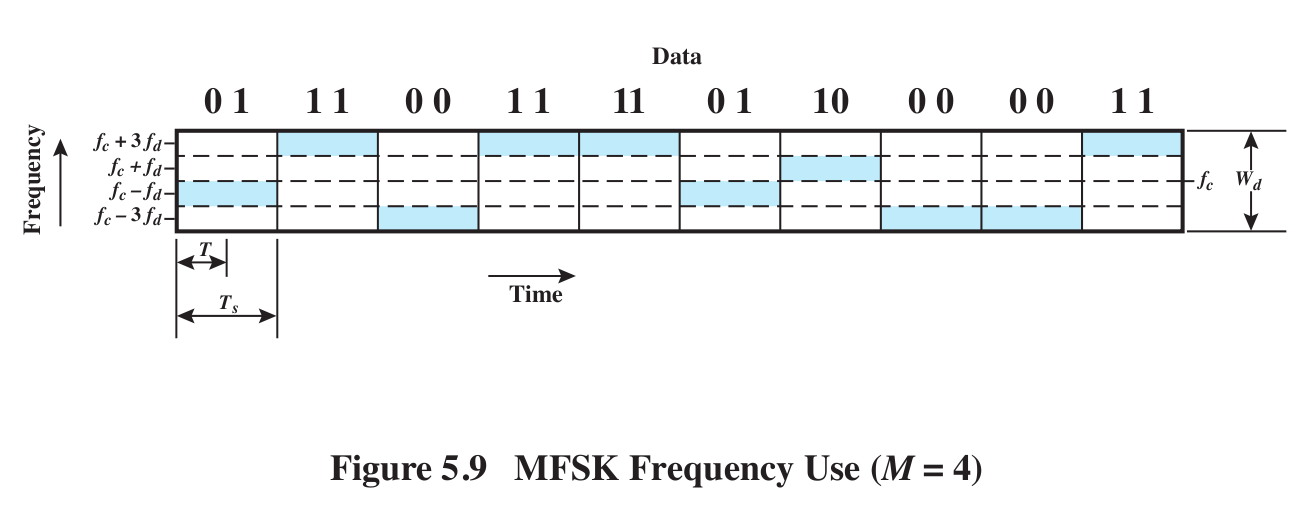
MFSK: multiple FSK; 2L frequencies to send L bits at a time (see Fig 5.9).

MFSK diagram
Review this simple example of MFSK.
Note one individual frequency is used to encode L bits; we need 2Lfrequencies in all to send all L-bit patterns. We are also sending the data two bits at a time, using the two bits to choose one of four frequencies. If we switched to binary, then we would only need two frequencies (two of the narrow horizontal bands). But for the same data rate we'd only have half as much time (Ts / 2) to identify each frequency, so each narrow band would have to be twice as wide. Bottom line: we'd have the same bandwidth requirement.

MFSK does a simple form of frequency hopping already. The goal of FHSS/MFSK is to greatly increase the hopping range

FHSS
We will use a "pseudo-noise" or pseudo-random (PN) sequence to spread the frequencies of MFSK over multiple "blocks"; each MFSK instance uses one block. Each endpoint can compute the PN sequence, but to the world in between it appears random. For each distinct PN symbol we will use a band like the MFSK band above, but we'll have multiple such bands all stacked together, a different band for each distinct PN symbol.
Tc: time for each unit in the PN sequence
Ts: time to send one block of L bits

slow v fast FHSS/MFSK: Fig 9.4 v 9.5
slow: Tc >= Ts: send >= 1 block of bits for each PN tick
fast: Tc < Ts: use >1 PN tick to send each block of bits

feature of fast: we use two or more frequencies to transmit each symbol; if there's interference on one frequency, we're still good.

Consider 1 symbol = 1 bit case

If we use three or more frequencies/symbol, we can resolve errors with "voting"

What is this costing us?